Organic single flow battery

A flow battery, single-liquid technology, applied in the direction of fuel cells, battery electrodes, battery components, etc., can solve the problems of cycle life, less maintenance, complex structure, etc., and achieve less maintenance, high energy efficiency, energy density and power density high effect

Inactive Publication Date: 2010-11-03
NO 63971 TROOPS PLA
View PDF0 Cites 37 Cited by
  • Summary
  • Abstract
  • Description
  • Claims
  • Application Information

AI Technical Summary

Problems solved by technology

[0006] The present invention proposes a single-flow battery based on solid organic matter, combining the characteristics of solid organic matter and liquid flow storage, using the manufacturing technology of organic solid electrodes for flow batteries, and forming a single-flow batte

Method used


Image

  • Organic single flow battery
  • Organic single flow battery
  • Organic single flow battery

Examples


Embodiment 1

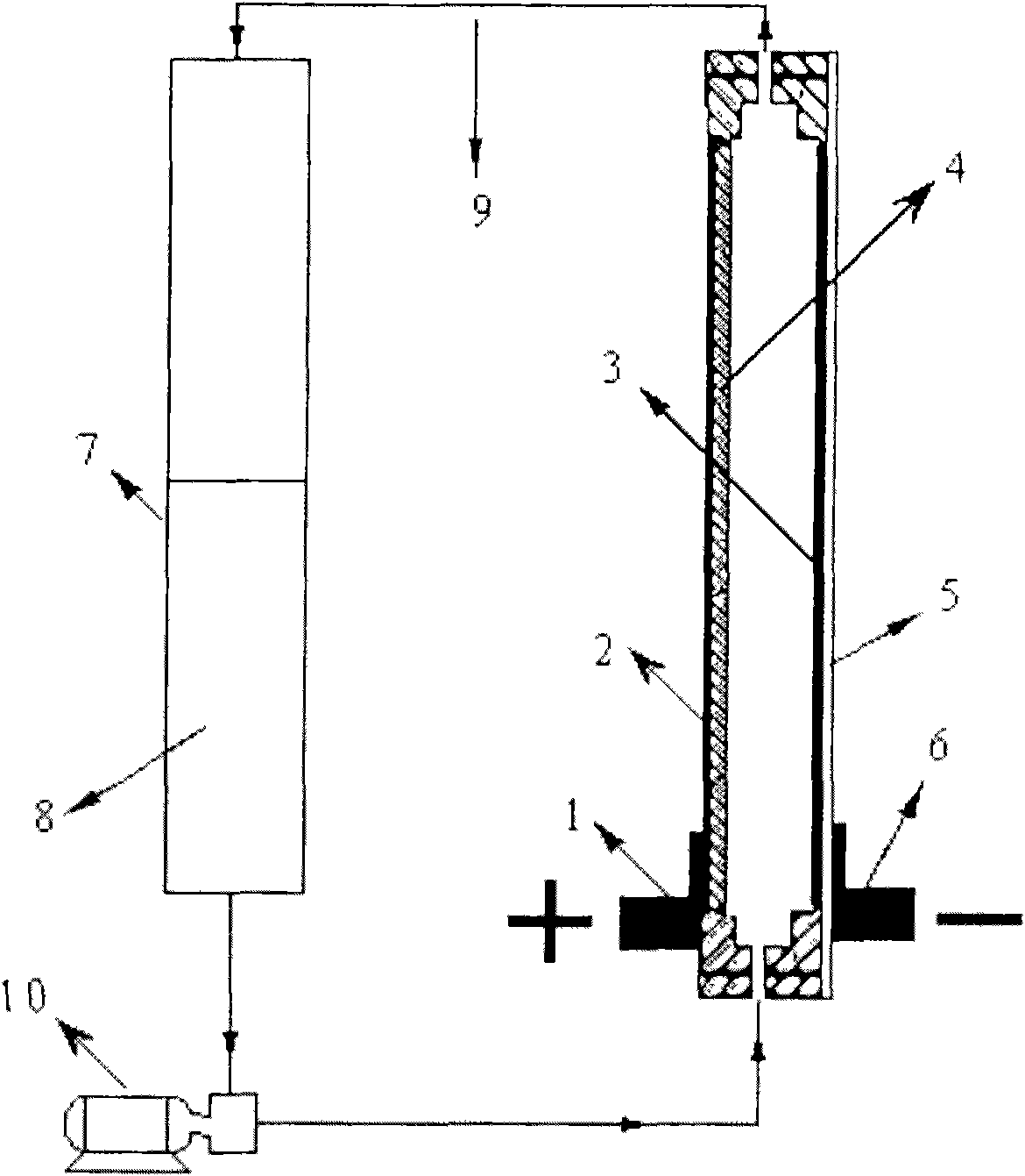
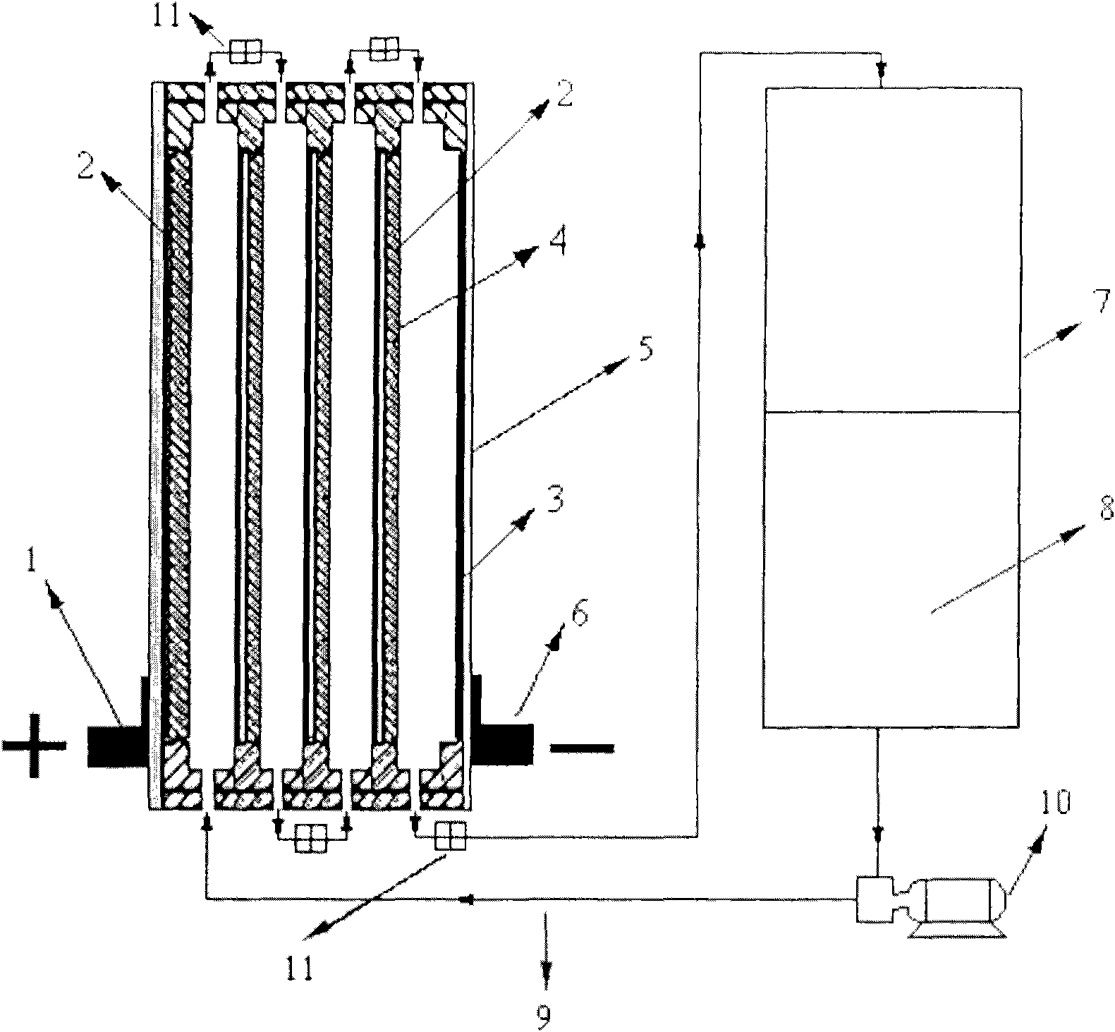
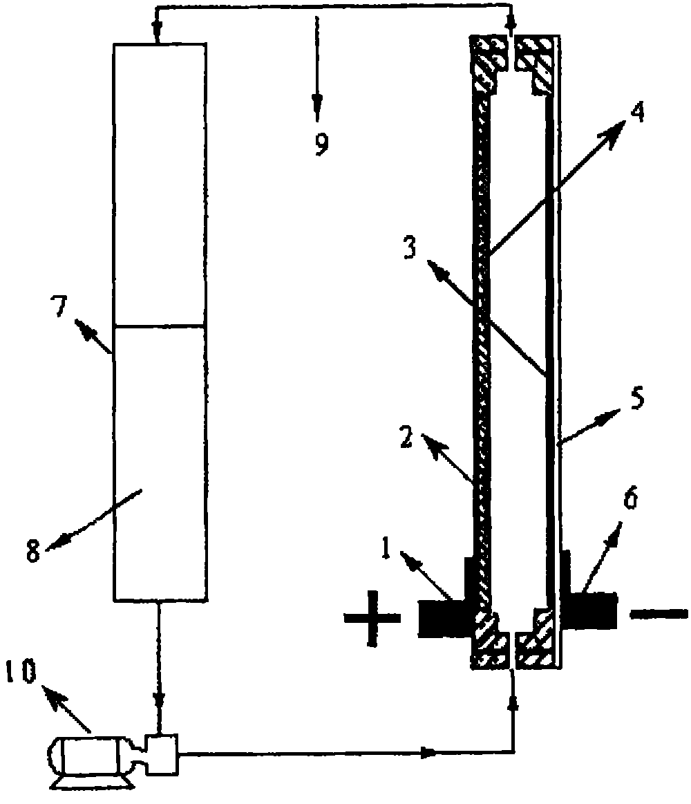
[0031] Mix the ball-milled chloranil with 40% graphite powder and 10% PTFE binder and press it into a sheet, press it on the graphite current collector with a conductive adhesive, and get a surface capacity of 2mAh after pre-discharge cm -2 organic solid electrodes. at 1.5cm 2 The titanium-based lead-plated electrode is the negative current collector, and 50mL of 1M H 2 SO 4 +1M Na 2 SO 4 +0.5M CdSO 4 The solution is an electrolyte. The MP-10RN magnetic circulation pump is used as the power pump to circulate the electrolyte over the positive / negative electrode surface of the battery. The open circuit voltage of the battery is about 1.20V, at 5mA·cm -2 The average discharge voltage is about 1.10V, the energy efficiency of this process is about 88%, the charge and discharge cycle is 50 times, and the battery performance decay rate is less than 5%.

Embodiment 2

[0033] Mix the ball-milled chloranil with 50% graphite powder and 5% PTFE binder and press it into a sheet, press it on the graphite current collector with a conductive adhesive, and obtain a surface capacity of 2mAh after pre-discharge cm -2 organic solid electrodes. at 1.5cm 2 The titanium-based galvanized electrode is the negative current collector, and 50mL of 3M NH 4 Cl+1.0M ZnCl 2 The solution is an electrolyte. The MP-10RN magnetic circulation pump is used to circulate the electrolyte over the positive / negative electrode surface of the battery. The open circuit voltage of the battery is about 1.10V, at 10mA·cm -2 The average discharge voltage is about 1.0V, the energy efficiency of this process is about 81%, the charge and discharge cycle is 50 times, and the battery performance decay rate is less than 10%.

Embodiment 3

[0035] The double-sided lamination rated surface capacity is 2mAh cm -2 The graphite plate of tetrachlorophenol is the positive electrode, with 1*1.5cm 2 The lead-plated nickel mesh electrode is the negative current collector, 100mL of 0.5MH 2 SO 4 +1MK 2 SO 4 +0.5M CdSO 4 The aqueous solution is an electrolyte, and 0.5 g / L of gelatin is added to the electrolyte. The MP-10RN magnetic circulation pump is used as the infusion pump to circulate the electrolyte over the positive / negative electrode surface of the battery. The open circuit voltage of the battery is 1.20V, 10mA cm -2 The average discharge voltage is about 1.10V, the energy efficiency of this process is about 85%, the charge and discharge cycle is 50 times, and the battery performance decay rate is less than 10%.


PUM


Abstract

The invention relates to an organic single flow battery used for large-scale energy storage. The organic single flow battery comprises an electrolyte storage tank, a deposited metal cathode and a solid organic matter anode. Aqueous solution containing soluble and precipitable metal ions is taken as electrolyte and passes through the surface of the anode/cathode through pump circulation. During charging, the metal ions in the electrolyte are deposited to a current collector of the cathode, and low valent solid organic matters on the anode are converted into high valent solid organic matters; and during discharging, metal from the current collector of the cathode is dissolved in the electrolyte, and the high valent solid organic matters on the anode are converted into low valent solid organic matters. Compared with the traditional flow battery, the organic single flow battery does not need a diaphragm so as to avoid cross contamination of solution of the two poles, and has the characteristics of simple structure, convenient preparation, high electric energy conversion rate, long service life, environmental protection, safe use and the like.

Description

technical field [0001] The invention relates to the principle and preparation of a static organic single-flow battery, which belongs to the field of chemical industry and can be widely used in non-grid-connected renewable energy power generation, large-scale energy storage in factories, mines, buildings, and remote areas, as well as peak shaving and valley addition of power grids. . Background technique [0002] Liquid flow batteries are developed from fuel cells. Since the concept was proposed in 1974, they have attracted widespread attention due to their many unique properties. Different from the solid-state active material contained in the anode and cathode of the usual battery, the high and low potential two oxidation-reduction couples used as the active material in the flow battery, two or one of them are dissolved in the liquid storage tank In solution, the solution is pumped through the cell, where oxidation and reduction reactions take place on inert solid electrode...

Claims


Application Information

Patent Timeline
IPC IPC(8): H01M8/18H01M4/60H01M4/64H01M4/02H01M4/62H01M2/40H01M8/24H01M2/22H01M8/2455H01M50/528H01M50/77
CPCY02E60/528Y02E60/50Y02E60/10
Inventor 文越华程杰徐艳杨裕生谢自立
Owner NO 63971 TROOPS PLA
Why Eureka
Try Eureka