

CrTiAlSiN nano composite coating, cutter deposited with same and preparation method thereof
A nano-composite coating and composite coating technology, applied in the direction of tools, coatings, metal material coating processes for lathes, etc., can solve the problem of difficult to meet the comprehensive requirements of tool coatings, reduce internal stress, The effect of improving bonding strength and improving adhesion
- Summary
- Abstract
- Description
- Claims
- Application Information
AI Technical Summary
Problems solved by technology
Method used
Image

Examples
Embodiment 1
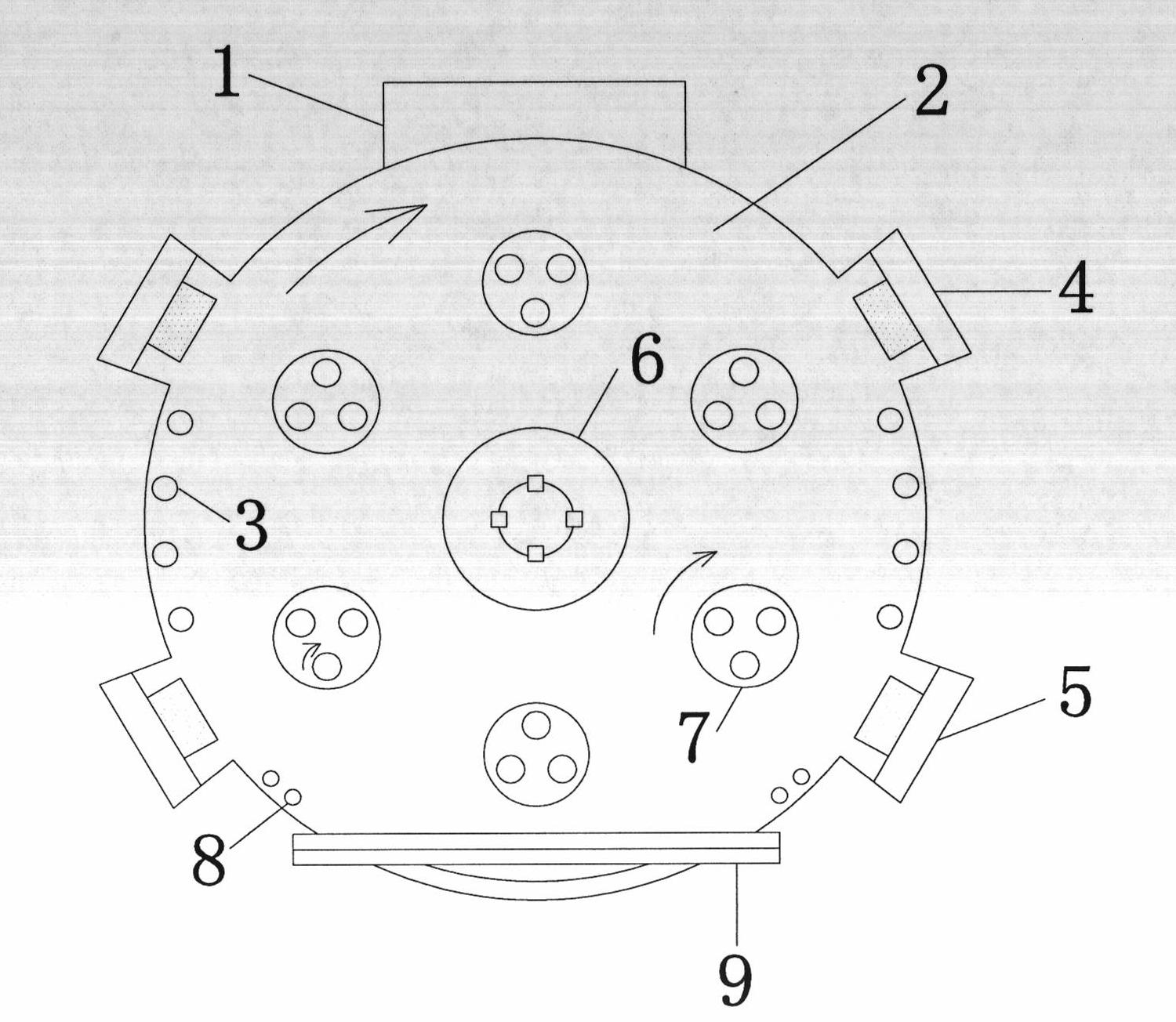
[0027] First, clean the carbide tool, clamp it on the workpiece frame, and start vacuuming. When the vacuum degree is higher than 5×10 -3 At Pa, start heating and degassing, the temperature is controlled at 300°C, and the revolution speed of the workpiece holder is 3 rpm. When the vacuum degree is 5×10 -3 At Pa, Ar gas is introduced, the temperature is controlled at 300°C, the bias power is turned on, the bias voltage is controlled at -800V, and the tool substrate is glow cleaned for 30 minutes. After the glow cleaning is finished, the vacuum degree is adjusted to 2×10 -2 Pa, the bias voltage is kept at -800V, the temperature is controlled at 300°C, open the Cr target, bombard the tool substrate for 10 minutes, and obtain a Cr bonding layer with a thickness of 70 nm; after the bombardment is completed, adjust the bias voltage to -200V, and close the Ar gas channel, into N 2 The vacuum degree was adjusted to 2.0 Pa, and the temperature was 300° C., and deposited on the Cr bo...
Embodiment 2
[0029] Clean the hard alloy tool, clamp it on the workpiece frame, and start vacuuming. When the vacuum degree is higher than 5×10 -3 Pa, start heating and degassing, control the temperature at 370°C, keep the revolution speed of the workpiece holder at 9 rpm, when the vacuum degree is 5×10 -3 At Pa, Ar gas was introduced, the temperature was controlled at 370°C, the bias power was turned on, and the bias voltage was controlled at -800V, and the tool substrate was glow-cleaned, and the glow time was 40 minutes. After glow cleaning, in a vacuum of 1.5×10 -2 Pa, at a temperature of 370°C and a bias voltage of -800V, open the Cr target, and bombard the tool substrate for 15 minutes to obtain a 100 nm-thick Cr bonding layer; after the bombardment, close the Ar gas channel and inject N 2 Adjust the vacuum degree to 2.0Pa, adjust the bias voltage to -250V, control the temperature at 370°C, and deposit on the Cr bonding layer for 5 minutes to obtain a 100nm thick CrN support layer. ...
Embodiment 3
[0031] Clean the hard alloy tool, clamp it on the workpiece frame, and start vacuuming. When the vacuum degree is higher than 5×10 -3 Pa, start heating and degassing, the temperature is controlled at 350°C, and the revolution speed of the workpiece holder is kept at 11 rpm. When the vacuum degree is 5×10 -3 At Pa, Ar gas was introduced, the temperature was controlled at 350°C, the bias power was turned on, and the bias voltage was controlled at -800V, and the tool was glow cleaned for 45 minutes. After glow cleaning, the vacuum degree is adjusted to 2.2×10 -2 Pa, the temperature is controlled at 350°C, and the bias voltage is maintained at -900V. Turn on the Cr target and bombard the tool substrate for 15 minutes to obtain a Cr bonding layer with a thickness of 80 nanometers; Gas, feed N 2 The vacuum degree was adjusted to 2.0Pa, the temperature was controlled at 350°C, and the CrN bonding layer was deposited for 10 minutes to obtain a 200nm thick CrN support layer. After t...
PUM
| Property | Measurement | Unit |
|---|---|---|
| Thickness | aaaaa | aaaaa |
| Thickness | aaaaa | aaaaa |
| Adhesion | aaaaa | aaaaa |
Abstract
Description
Claims
Application Information