Ultrasonic standing wave type micro-fluidic chip and preparation method thereof

A microfluidic chip, ultrasonic standing wave technology, applied in the field of micro-total analysis system, can solve the problems of lack of chip operability and controllability research, acoustic wave chip stay, unfavorable marketization, etc. Controllable adjustment and simple processing effect

Active Publication Date: 2010-11-10
WUHAN UNIV
View PDF9 Cites 23 Cited by
  • Summary
  • Abstract
  • Description
  • Claims
  • Application Information

AI Technical Summary

Problems solved by technology

The processing effect of this kind of acoustic wave chip is better, but it needs to use anode bonds and equipment worth millions, so that the cost of the prepared chip is very high, which is ...

Method used


Image

  • Ultrasonic standing wave type micro-fluidic chip and preparation method thereof
  • Ultrasonic standing wave type micro-fluidic chip and preparation method thereof
  • Ultrasonic standing wave type micro-fluidic chip and preparation method thereof

Examples


Embodiment 1

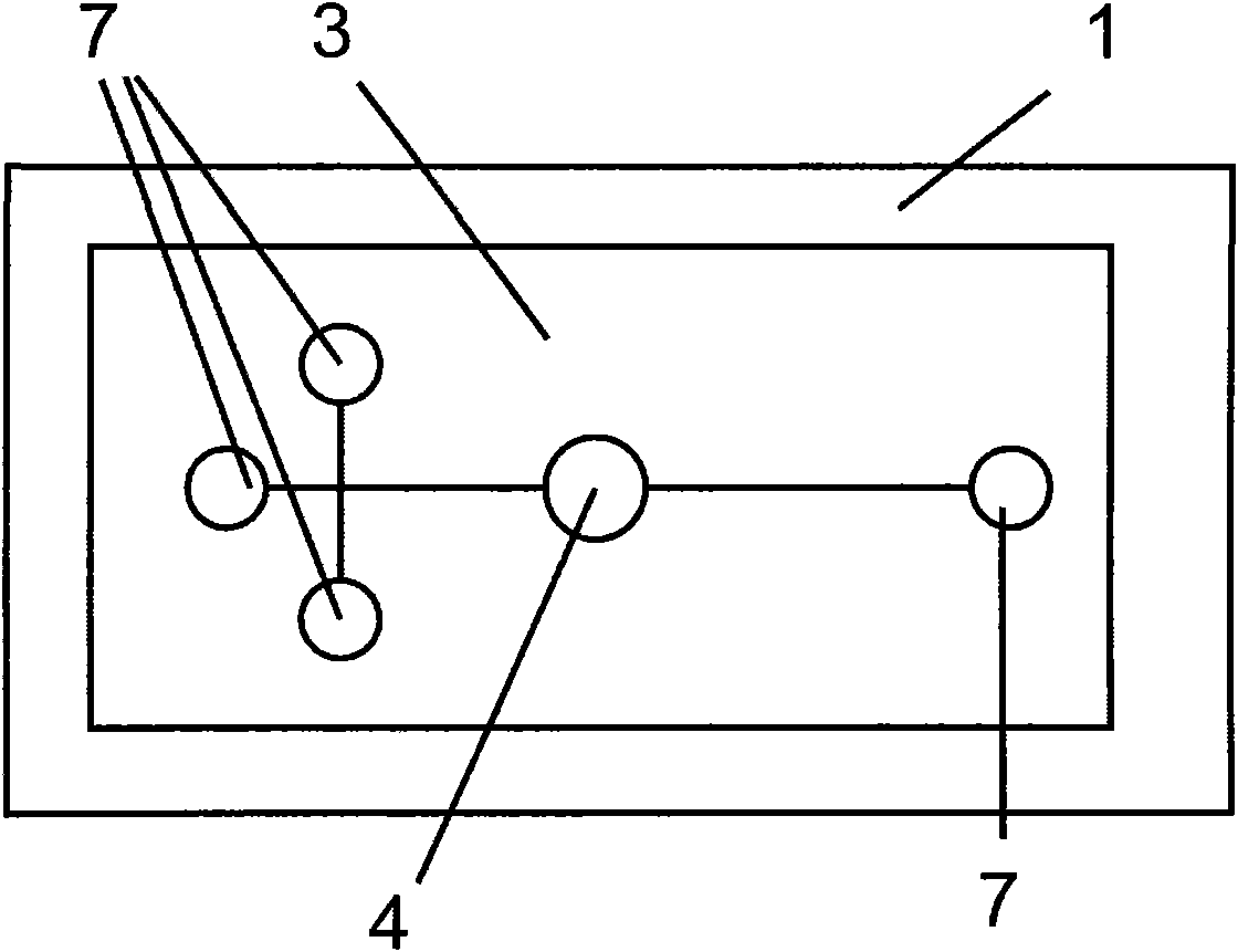
[0023] 1. Use the method of soft lithography to prepare the single crystal silicon positive mold template for the ultrasonic standing wave microfluidic chip. Only one standing wave reaction chamber (4) is designed in this template, forming a 1×1 standing wave reaction chamber array;

[0024] 2. Process a hole corresponding to the structure in the microfluidic chip on the PCB board (1) plated with a layer of copper on the surface, and install and fix the PZ26 piezoelectric ceramic sheet in the hole of the ultrasonic standing wave reaction chamber ( 5), as the sound source of the ultrasonic standing wave, wiring is carried out on the back of the PCB board (1) at the same time, and the input signal of the piezoelectric ceramic sheet (5) is connected to the output end of the control circuit;

[0025] 3. Pour the PDMS liquid prepolymer (2) on the positive mold template, and then put a glass slide (3) on the PDMS liquid prepolymer (2) on the male mold template. Demoulding, making a...

Embodiment 2

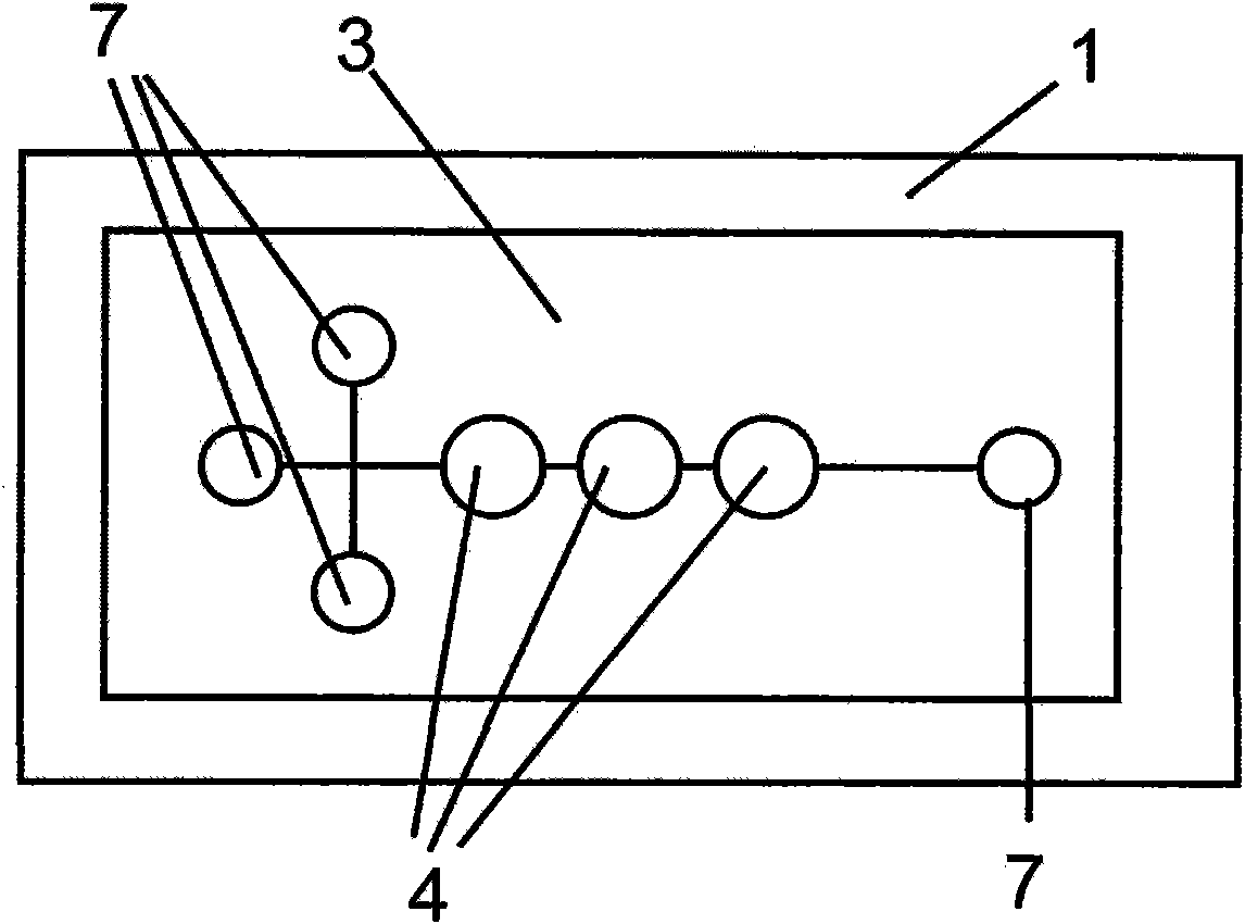
[0028] 1. The glass positive mold template for the ultrasonic standing wave microfluidic chip is prepared by soft lithography. Three standing wave reaction chambers (4) are designed in the template to form a 1×3 standing wave reaction chamber array;

[0029] 2. Process holes corresponding to the structure in the microfluidic chip on the PCB (1) coated with a layer of platinum on the surface, and install and fix three PZ26 pressure gauges in the holes corresponding to the ultrasonic standing wave reaction chamber. The electric ceramic sheet (5), as the sound source of the ultrasonic standing wave, is wired on the back of the PCB board (1) at the same time, and all the input signals of the piezoelectric ceramic sheet (5) are connected to the output ends of the three-way switch circuit, and Fix the circuit board welded with the three-way switch on both sides of the PCB board (1) as a bracket;

[0030] 3. Pour the PDMS liquid prepolymer (2) on the positive mold template, and then ...

Embodiment 3

[0033] 1. The monocrystalline silicon positive mold template for the ultrasonic standing wave microfluidic chip is prepared by soft lithography, and 9 standing wave reaction chambers (4) are designed in the template to form a 3×3 array distribution;

[0034] 2. Process holes corresponding to the structure in the microfluidic chip on the PCB plated with a layer of gold on the surface, and install and fix nine PZ26 pressure sensors in the holes of the ultrasonic standing wave reaction chamber (4). The electric ceramic sheet (5), as the sound source of the ultrasonic standing wave, is wired on the back side of the PCB board (1) at the same time, and all the input signals of the piezoelectric ceramic sheet (5) are connected to the output ends of the nine-way switch circuit, and Fix the circuit board welded with the nine-way switch on both sides of the PCB board (1) as a bracket;

[0035] 3. Pour the PDMS liquid prepolymer (2) on the positive mold template, and then put a glass sli...


PUM


Abstract

The invention discloses an ultrasonic standing wave type micro-fluidic chip and a preparation method thereof. The ultrasonic standing wave type micro-fluidic chip comprises a glass slide, a micro-fluidic chip, a printed circuit board (a PCB board), a piezoelectric ceramic and a control circuit. The micro-fluidic chip comprises a standing wave reaction chamber and is formed through curing of liquid polydimethylsiloxane (PDMS) prepolymer with a male template, the glass slide is arranged on the micro-fluidic chip prior to curing, and the mold is released after curing the glass slide and the micro-fluidic chip as a whole; the front face of the PCB board is plated with a conductive layer and is connected with the micro-fluidic chip as a whole through the conductive layer and the non-slide surface of the micro-fluidic chip, hole sites corresponding to the micro-fluidic chip are also arranged on the front face of the PCB board, and the piezoelectric ceramic is arranged in a hole site corresponding to the standing wave reaction chamber; and the control circuit is arranged on the back face of the PCB board. The invention has the advantages of simple manufacture, low cost, high controllability, high maneuverability and high degree of integration, and can easily realize the separation, capture and manipulation of cells and samples of other biological living bodies.

Description

technical field [0001] The invention belongs to the field of micro total analysis system. In particular, it relates to an ultrasonic standing wave microfluidic chip and a preparation method thereof. Background technique [0002] Microfluidic chip technology was developed in the field of analytical chemistry in the 1990s. It is characterized by micro-networks and life sciences as the main research object. The functions of the entire laboratory include sample pretreatment, reaction, separation, and detection. etc. are integrated on the microchip, which greatly improves the analysis speed, has extremely wide applicability and application prospects, and is the focus of current micro-analysis system research. [0003] At the same time, due to the nondestructiveness of acoustic detection and operation methods for the detection of living biological samples, it has become another research hotspot. At present, in the microfluidic system, the micro-network structure is generally etc...

Claims


Application Information

Patent Timeline
IPC IPC(8): G01N35/00
Inventor 国世上赵兴中郭峰李思晢曾谦
Owner WUHAN UNIV
Why Eureka
Try Eureka