Opposite-emitting type optical fiber coupling auxiliary regulating device and coupling method
A technology of through-beam optical fiber and adjustment device, which is applied in the field of optical fiber, can solve the problems of difficulty in adjustment, difficulty in adjustment, and impossibility of application, etc., and achieve the effect of convenient use, simple device, and simple and clear adjustment process
- Summary
- Abstract
- Description
- Claims
- Application Information
AI Technical Summary
Problems solved by technology
Method used
Image

Examples
Embodiment Construction
[0029] The present invention will be further described below in conjunction with the embodiments and accompanying drawings, but the protection scope of the present invention should not be limited thereby.
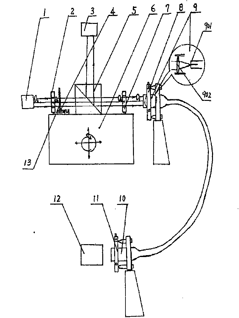
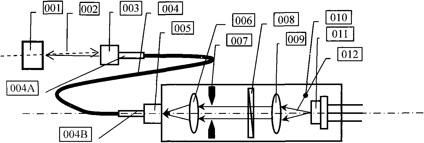
[0030] see first figure 2 , figure 2 It is a structural schematic diagram of the through-beam optical fiber auxiliary adjustment device of the present invention. It can be seen from the figure that the composition of the through-beam optical fiber coupling auxiliary adjustment device of the present invention is: the laser diode 011, the collimator lens 009, and the half-wave plate 008 are sequentially connected on the same optical axis. , diaphragm 007, coupling lens 006 and fiber optic connector 005 are arranged on a base 010, the light-emitting surface of the laser diode 011 is located at the front focal plane of the collimator lens 009, and the fiber optic connector 005 The center of the fiber end face is located at the focal point of the coupling lens 006 .
[0031]...
PUM
 Abstract
Description
Claims
Application Information