Charge pump circuit used for reducing current mismatch at extra-low voltage in phase-locked loop

A charge pump and phase-locked loop technology, applied in the field of charge pump circuits, can solve the problems of increasing CP-PLL output spectrum reference spurs, insufficient power supply voltage drive capability, and small charge pump output impedance to achieve good matching and low voltage drop reduction, the effect of an increase in output impedance

Inactive Publication Date: 2010-11-17
ZHEJIANG UNIV
View PDF6 Cites 17 Cited by
  • Summary
  • Abstract
  • Description
  • Claims
  • Application Information

AI Technical Summary

Problems solved by technology

In addition, the charge pump with this structure, because the switch tube and the output of the charge pump are directly connected, the charge sharing effect is particularly obvious, and the current tube has experienced a process from linearity to saturation, which may easily cause charge and discharge current mismatch.
[0006] When the MOS switch tube is placed at the source, although the switch tube is not directly connected to the output, it is less affected by the charge injection effect, and the current tube always works in the saturation region, which can eliminate the charge sharing effect, but the switch tube is also con...

Method used


Image

  • Charge pump circuit used for reducing current mismatch at extra-low voltage in phase-locked loop
  • Charge pump circuit used for reducing current mismatch at extra-low voltage in phase-locked loop
  • Charge pump circuit used for reducing current mismatch at extra-low voltage in phase-locked loop

Examples


Embodiment Construction

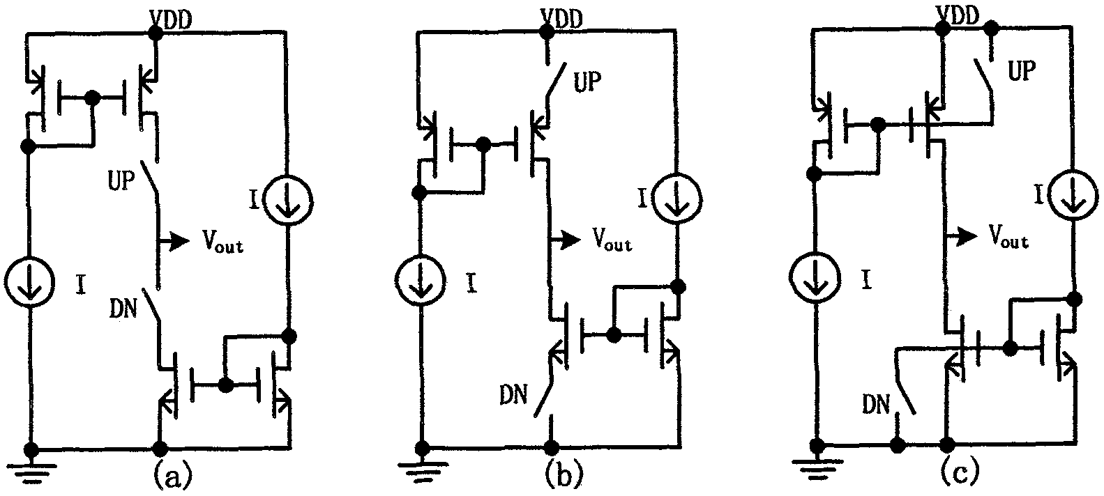
[0030] like figure 1 In the circuit structures of the three traditional charge pump circuits described above, a MOS tube is used as a switch tube to control charge and discharge of the charge pump circuit.

[0031] figure 1 As shown in (a), the MOS switching tube is placed at the drain, the switching tube is connected in series with the current tube, and the switching tube is directly connected to the output of the charge pump. Under extremely low working voltage, the power supply voltage is not enough to drive two cascaded MOS tubes, and the current tube has gone through the process from linearity to saturation region, which is easy to cause mismatch of charge and discharge current.

[0032] figure 1 As shown in (b), the MOS switching tube is placed at the source, and the switching tube is connected in series with the current tube. Under the extremely low working voltage, there is also the problem of insufficient driving capability of the power supply voltage.

[0033] lik...


PUM


Abstract

The invention discloses a charge pump circuit used for reducing current mismatch at an extra-low voltage in a phase-locked loop. The charge pump comprises a gate current mirror, a pull-up circuit, a pull-down circuit and an operational amplifier, wherein the gate current mirror consists of a first p-metal oxide semiconductor (PMOS) device, a second PMOS device and a first n-metal oxide semiconductor (NMOS) device; the pull-up circuit consists of a third PMOS device, a fourth PMOS device, a first switch and a second switch; the pull-down circuit consists of a second NMOS device, a third NMOS device, a third switch and a fourth switch; the fourth PMOS device realizes the functions of both a pull-up current tube and a pull-up switching tube; and the third NMOS device realizes the functions of both a pull-down current tube and a pull-down switching tube, so that the charge pump circuit realizes the parallel connection of the switching tubes and the current tubes and is suitable to work in an environment of low power supply voltage. A feedback loop formed by the operation amplifier increases the output impedance and reduces the mismatch of charging and discharging current.

Description

technical field [0001] The invention relates to the technical field of integrated circuits, in particular to a charge pump circuit for reducing current mismatch under extremely low voltage operation in a phase-locked loop. Background technique [0002] The charge pump phase-locked loop (CP-PLL) has the characteristics of high speed and low noise, so it has become the most common phase-locked loop circuit today, and is widely used in various communication circuits, frequency synthesizers and clock recovery circuits. The charge pump circuit plays a very important role in the CP-PLL. Its main function is to integrate the pulse reflecting the phase difference between the output signal and the input signal, and output the result of the integration in the form of voltage variation, and then use this output The voltage controls the frequency of the VCO. [0003] With the development of microelectronics technology in the direction of nanometer size, integrated circuit design is req...

Claims


Application Information

Patent Timeline
IPC IPC(8): H02M3/07
Inventor 梁筱韩雁杨伟伟程维维
Owner ZHEJIANG UNIV
Why Eureka
Try Eureka