Super-gravity revolving bed provided with multi-layer cylindrical rotary liquid distributor

A high-gravity rotating bed and liquid distributor technology, applied in chemical/physical/physicochemical fixed reactors, fractionation, separation methods, etc., can solve the troublesome production and installation, troublesome production and installation of distributors, high initial distribution requirements, etc. problems, to achieve the effect of simple structure, easy equipment and high mass transfer efficiency

Active Publication Date: 2010-11-24
ZHEJIANG UNIV OF TECH
View PDF11 Cites 20 Cited by
  • Summary
  • Abstract
  • Description
  • Claims
  • Application Information

AI Technical Summary

Problems solved by technology

The liquid is distributed by the centrifugal force generated by the rotation, which improves the operating range of the liquid flow, but this type of liquid distributor needs a dynamic sealing structure between the liquid feed pipe, the structure of the distributor is complicated, and the production and installation are troublesome; the liquid is axially distributed in the liquid distribution pipe. uneven distribution
[0004] Chinese patents CN 101254356A and CN101254357A disclose the concentric ring counterflow type supergravity rotating bed device, which has the advantages of high mass transfer efficiency, easy realization of intermediate feeding, and convenient multi-layer installation. However, this type of rotating bed requires relatively high initial distribution of liquid. High, whether the liquid distribution is uniform or not directly affects the mass transfer performance of the equipment
The layer-by-layer partition distributor and stepped distributor used in this type of device can achieve the initial distribution of the liquid, but the liquid is not evenly distributed in the axial direction of the moving disk, and the void ratio of the distributor is low, which is easy to flow in the tower. It forms the bottleneck of the gas channel, and the manufacture and installation of the distributor is troublesome

Method used


Image

  • Super-gravity revolving bed provided with multi-layer cylindrical rotary liquid distributor
  • Super-gravity revolving bed provided with multi-layer cylindrical rotary liquid distributor
  • Super-gravity revolving bed provided with multi-layer cylindrical rotary liquid distributor

Examples


Embodiment 1

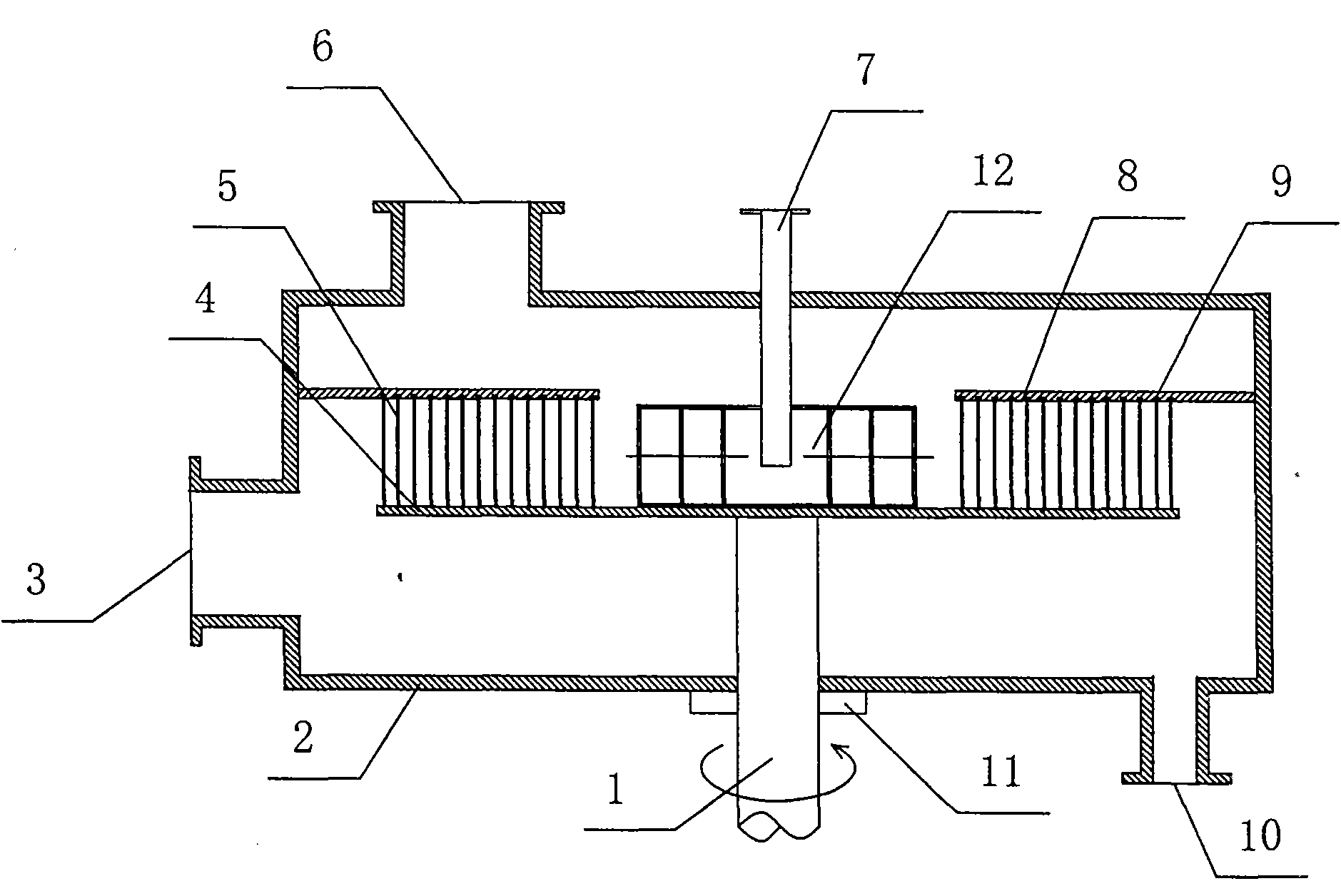
[0024] Such as figure 1 Shown is a single-layer concentric ring-type high-gravity rotating bed device with a multi-layer sleeve-type rotating liquid distributor, which includes a shell 2, a stationary disk 8, a rotating shaft 1, a rotor 4, and a multi-layer cylindrical rotating liquid distributor 器12. The upper end of the casing 2 is provided with a gas outlet 6 and a liquid inlet 7, the lower end of the casing 2 is provided with a gas inlet 3 and a liquid outlet 10, and a mechanical seal 11 is installed at the joint between the rotating shaft 1 and the casing 2. The center of the housing 2 is provided with a rotating shaft 1 and a stationary disk 8, the stationary disk 8 is fixedly connected to the housing 2, the rotating shaft 1 is fixedly connected to a rotor 4, and the rotor 4 is fixedly connected to the multilayer sleeve type liquid distributor 12. The rotor 4 is a concentric ring rotor. A set of concentric moving rings 5 ​​with screen holes of different diameters are provi...

Embodiment 2

[0028] Such as Figure 4 Shown is a single-layer packed high-gravity rotating bed device with a multi-layer sleeve-type rotating liquid distributor. This embodiment is completely the same as Embodiment 1 except that the rotor and sealing structure are different from Embodiment 1. This embodiment adopts Figure 4 In the shown packed rotor, the lower end of the ring-shaped packing layer 18 is fixedly connected to the rotor 4. In order to prevent gas short circuit, a dynamic sealing structure 9 is provided between the upper end of the packing layer 18 and the stationary disk 8, and the gas and liquid flow backward in the rotor 4. After the contact, the gas is discharged from the gas outlet 6 and the liquid phase is discharged from the liquid outlet 10.

Embodiment 3

[0030] Such as Figure 5 Shown is a three-layer concentric-circle counter-current high-gravity rotating bed device with a multi-layer sleeve-type rotating liquid distributor. Each layer of the rotor includes a multi-layer sleeve-type liquid distributor 12 fixedly connected to the rotor. The upper end of the rotor is fixedly connected to the housing 2 and the upper end surface of the stationary disk 8 is provided with a fixedly connected drainage tube 19 and a retaining ring 20, so One end of the drainage tube 19 is communicated with the retaining ring 20, and the lower end of the other end extends into the feed tank 13 of the multilayer sleeve type liquid distributor 12.


PUM


Abstract

The invention relates to a super-gravity revolving bed provided with a multi-layer cylindrical rotary liquid distributor. The revolving bed comprises a shell, a rotating shaft, a rotor and the multi-layer cylindrical rotary liquid distributor, wherein the multi-layer cylindrical rotary liquid distributor comprises a feed chute and a plurality of layers of cylinders; the middle of the multi-layer cylindrical rotary liquid distributor is provided with a cylindrical hollow feed chute which is communicated with a liquid inlet; the outer side face of the feed chute is provided with cylinders which are coaxially arranged at certain radial intervals and embedded layer upon layer; the inner wall of the feed chute and the inner wall of each layer of cylinder are provided with liquid outlet holes of which the number increases layer by layer; a liquid passage is formed by communicating the cylinders through the liquid outlet holes; and the liquid outlet hole on an outermost layer of cylinders corresponds to the inner edge of a rotor. The revolving bed has the advantages that: 1, liquid is initially and uniformly distributed well in a circumferential direction and an axial direction under the action of centrifugal force; 2, the revolving bed achieves higher mass transfer efficiency; and 3, the structure is more simple, compact and reasonable and equipment is easy to manufacture and install.

Description

Technical field [0001] The invention relates to the field of supergravity rotating beds, in particular to a supergravity rotating bed with a multilayer cylindrical rotating liquid distributor. Background technique [0002] The supergravity field technology is a breakthrough technology to enhance the transfer and multiphase reaction process. Utilizing the highly enhanced mass transfer process and micro-mixing process characteristics in the supergravity environment, the chemical tower equipment up to tens of meters can be replaced with a supergravity machine less than two meters in height, so the supergravity rotating bed is known as the chemical equipment The "transistor". The existing rotating bed mostly adopts a fixed liquid distribution method, that is: connect the liquid distributor with the casing or other fixed supports, the liquid inlet pipe is stationary, and the liquid is sprayed through the liquid distributor pipe on the liquid distributor by the pressure of the pump T...

Claims


Application Information

Patent Timeline
Patent Type & Authority Applications(China)
IPC IPC(8): B01D3/30B01D53/18B01J19/18
Inventor 李育敏计建炳王营徐之超李肖华王广全
Owner ZHEJIANG UNIV OF TECH
Why Eureka
Try Eureka