Rapid dehydration dryer

A rapid dehydration, dehydration and drying technology, applied in the field of rapid dehydration dryer, sludge dehydration or drying treatment, stools, etc., can solve the problems of inconvenient treatment, slow processing time, difficult separation, etc., and achieve dehydration High efficiency, reasonable use of heat energy, and time-saving effects

Inactive Publication Date: 2010-12-08
戴文育
View PDF4 Cites 8 Cited by
  • Summary
  • Abstract
  • Description
  • Claims
  • Application Information

AI Technical Summary

Problems solved by technology

[0002] At present, dehydration or drying treatment technology is used in many fields, most of which are single dehydration or drying methods that need to be stopped for re-operation, or the method of squeezing and pressing rollers, but the disadvantages are low work efficiency, inconvenient handling, poor effect, and slow speed, etc. For the development needs of many dehydration and drying fields in the society, the technical application of rapid and continuous operation is required to solve the time and efficiency problems; especially for some excrement and sludge treatment equipment produced by

Method used


Image

  • Rapid dehydration dryer
  • Rapid dehydration dryer
  • Rapid dehydration dryer

Examples


Embodiment Construction

[0017] specific implementation plan

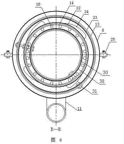
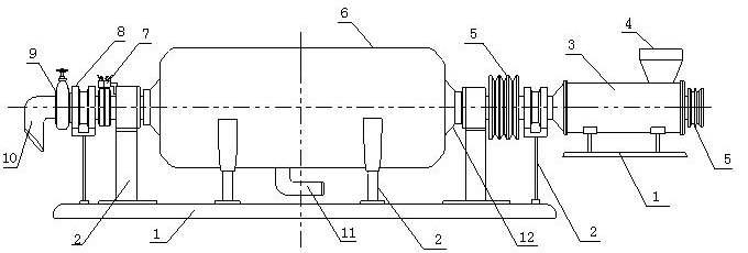
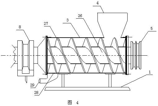
[0018] see figure 1 Among them, the structure diagram of the main body of the rapid dehydration dryer of the present invention is the main preferred option 1 of the present invention, which is characterized in that: a screw conveyor (3) is connected to a drum dehydration device for dehydration or drying treatment, and the material is conveyed by a screw Under the screw transport of the screw conveyor (3), the screw conveyor blade (27) at one end of the screw conveyor can be squeezed by the conical sleeve to squeeze the moisture of the material for the first time, and pass through the screen (28) and waste water The hole (29) discharges water, and the material is connected and transported to the drum dehydration device for dehydration or drying. In the process of processing, the outer drum (13) and inner drum (13) of the dehydration drum (12) 14) In the cavity, the material is conveyed while performing rapid spin dehydration. When the spin...


PUM


Abstract

The invention discloses a rapid dehydration dryer and relates to an environmental protection device for carrying out dehydration or spin-drying on slurry or slag particles related to industry, daily life, agriculture and the like, most of the treatment technologies which are adopted currently adopt the dehydration or the spin-drying method which solely needs the pause for re-operation or the shoving compression roller way, but such treatment technologies have low efficiency, inconvenient treatment, poor effects, slow speed and the like. The scheme is as follows: materials pass through a screw conveyor, the screw conveyor is further connected with a rotary drum dehydration device through a joint sleeve and a hollow shaft, the hollow shaft is arranged at two ends of the dehydration rotary drum, a belt pulley and a belt are arranged at one end of the hollow shaft, the end of the hollow shaft is connected onto a power source, a heating element is placed on the wall of an inner housing of the dehydration rotary drum, the dehydration rotary drum is supported by support bearings at two ends of the hollow shaft, a hood shell is arranged on the surface of the dehydration rotary drum, a water outlet pipe port is designed at the bottom end of the hood shell, and the other end of the hollow shaft is connected with the joint sleeve and connected to a discharge port; and the rapid dehydration dryer can carry out full dehydration, simultaneously reasonably utilize heat energy, effectively save the time, and solve the problems of slow speed and the like caused by adopting the pause spin-drying or a shoving compression roller in the traditional technologies.

Description

technical field [0001] The present invention relates to the dehydration or drying treatment of solid and liquid, and relates to the environmental protection equipment for dehydration or drying of slurry or slag particles related to industry, daily life, agriculture, etc., especially to the dehydration or drying treatment of feces and sludge , specifically a fast dehydration dryer. Background technique [0002] At present, dehydration or drying treatment technology is used in many fields, most of which are single dehydration or drying methods that need to be stopped for re-operation, or squeezing rollers, but the disadvantages are low work efficiency, inconvenient handling, poor effect, slow speed, etc. For the development needs of many dehydration and drying fields in the society, the technical application of rapid and continuous operation is required to solve the time and efficiency problems; especially for some excrement and sludge treatment equipment produced by existing ...

Claims


Application Information

Patent Timeline
IPC IPC(8): F26B11/04F26B25/12
Inventor 戴文育
Owner 戴文育
Why Eureka
Try Eureka