

Vacuum holding nozzle
A vacuum adsorption and adsorption surface technology, applied in the direction of manipulators, electrical components, chucks, etc., can solve the problems of adsorption deviation, inability to adapt to high-speed installation, vibration and sliding of electronic parts, etc., and achieve reliable adsorption effect
- Summary
- Abstract
- Description
- Claims
- Application Information
AI Technical Summary
Problems solved by technology
Method used
Image

Examples
no. 1 approach example
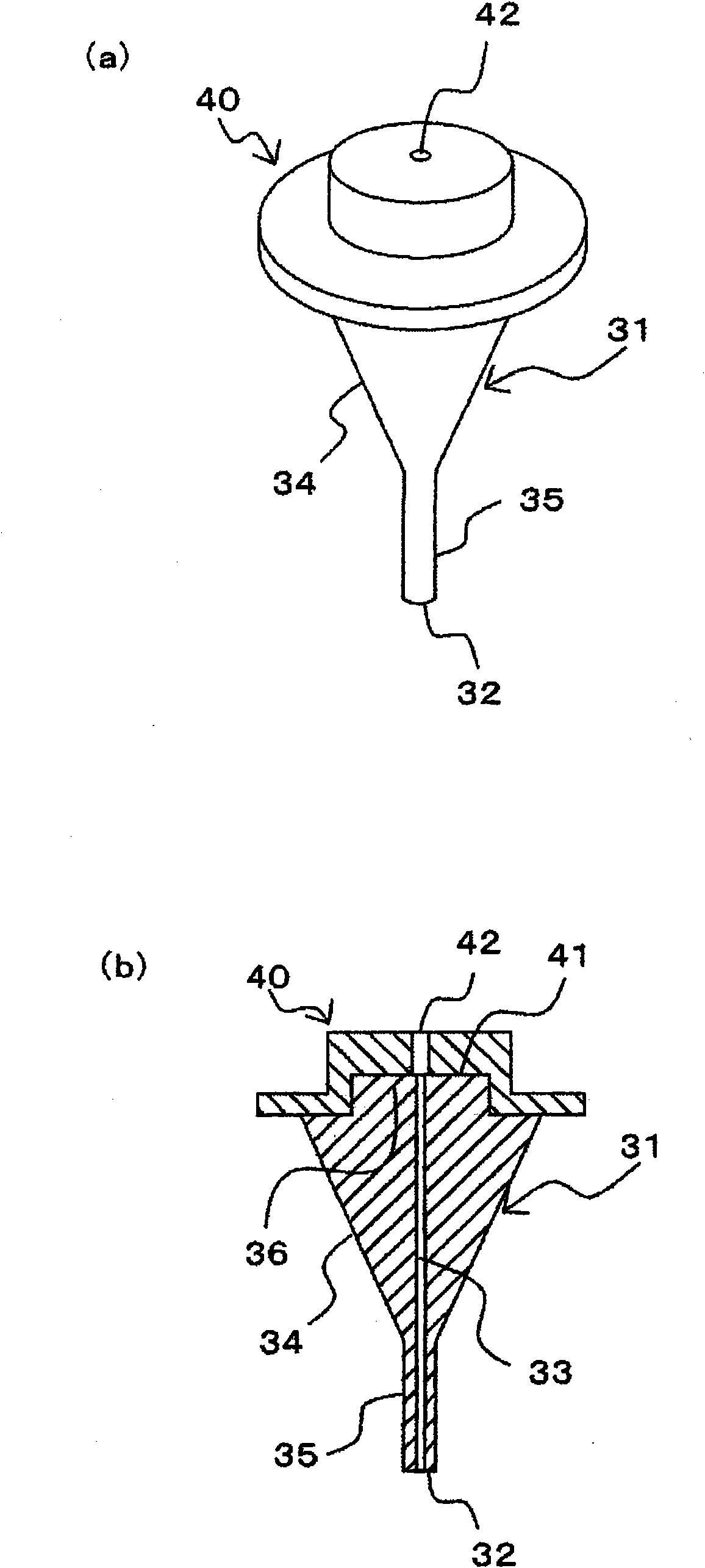
[0068] figure 1 It is a figure which shows an example of the structure when the vacuum suction nozzle which concerns on 1st Embodiment of this invention is assembled|attached to the holding member of an electronic component mounting machine, (a) is a perspective view, (b) is a longitudinal sectional view of (a).
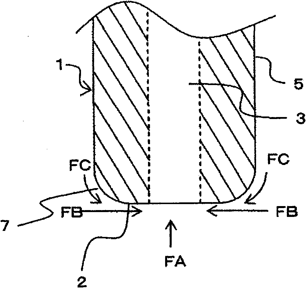
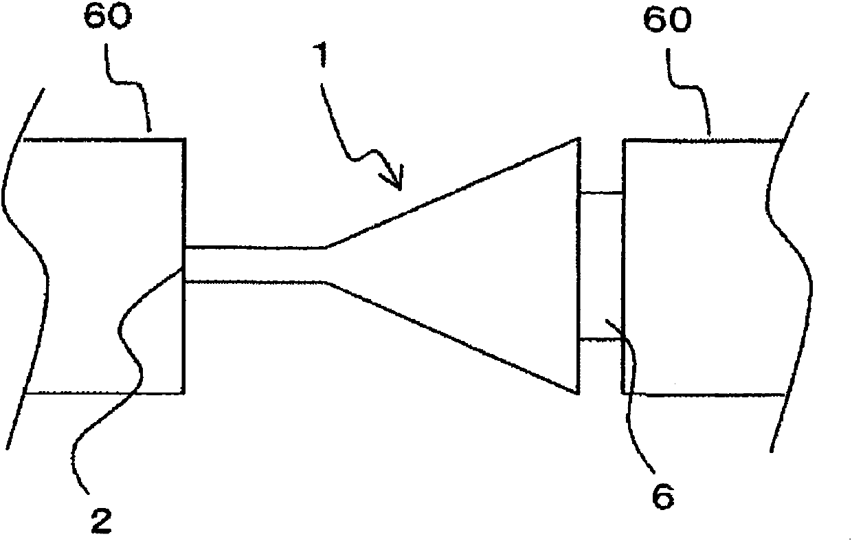
[0069] Such as figure 1 As shown, the vacuum suction nozzle 1 of the first embodiment of the present invention has: the end surface side of the front end has a cylindrical portion 5 for suctioning and holding the suction surface 2 of the electronic component by vacuum suction, and the suction surface of the cylindrical portion 5 is connected to the suction surface. 2, a conical portion 4 that is tapered toward the cylindrical portion 5 on one side opposite to the cylindrical portion 5, and a head 6 that is provided on the end face side of the root portion opposite to the adsorption surface 2. And the suction hole 3 is formed along the inner hole which penetrates t...
no. 2 approach
[0108] Next, an example of the second embodiment of the present invention will be described.
[0109] figure 1 It is a figure which shows an example of the structure when the vacuum suction nozzle of this invention is assembled|attached to the holding member of an electronic component mounting machine, wherein (a) is a perspective view, and (b) is a longitudinal sectional view of (a).
[0110] Such as figure 1 The shown vacuum suction nozzle 1 has: the end surface side of the front end has a cylindrical portion 5 for suctioning and holding an electronic component (not shown) by vacuum suction, and a cylindrical portion 5 on the suction surface with the cylindrical portion 5. 2, a conical portion 4 provided in a tapered shape toward the cylindrical portion 5 on the opposite side, and a head 6 provided on the end face side of the root portion opposite to the adsorption surface 2. In addition, the inner hole penetrating the cylindrical part 5 and opening on the suction surfac...
Embodiment 1
[0172] Next, examples of the present invention will be described.
[0173] Using stabilized zirconia containing 3 mol % of yttrium oxide as the main component and alumina as the second component, Sample Nos. 1 to 11 were produced. First, zirconia and alumina are put into different ball mills together with a solvent, and pulverized to a predetermined particle size to prepare a slurry. The slurry is mixed and spray-dried using a spray dryer to produce granules. The mixing ratio of zirconia and alumina was set to 90% by mass of zirconia and 10% by mass of alumina.
[0174] Next, the pellets, ethylene-vinyl acetate copolymer, polystyrene, and acrylic resin, which are thermoplastic resins, were put into a kneader. A total of 20% by mass of ethylene-vinyl acetate copolymer, polystyrene, and acrylic resin was added to 100% by mass of the pellets. Kneading was performed while maintaining the temperature of 150 degreeC, and the clay was produced. Then, the obtained kneaded clay was...
PUM
 Abstract
Description
Claims
Application Information