Biaxial MEMS reflective galvanometer and F-Theta lens-based linear scanning system used for laser heterodyne interferometer

A technology of laser heterodyne interference and linear scanning, which is applied in the field of scanning systems, can solve problems such as single wavelength and inability to realize linear and uniform scanning, and achieve the effect of improving the accuracy of lateral resolution

Inactive Publication Date: 2010-12-15
HARBIN INST OF TECH
View PDF0 Cites 16 Cited by
  • Summary
  • Abstract
  • Description
  • Claims
  • Application Information

AI Technical Summary

Problems solved by technology

[0006] In order to solve the problem that the existing optical scanning system is applicable to a single wavelength and cannot realize linear uniform scanning, th

Method used


Image

  • Biaxial MEMS reflective galvanometer and F-Theta lens-based linear scanning system used for laser heterodyne interferometer
  • Biaxial MEMS reflective galvanometer and F-Theta lens-based linear scanning system used for laser heterodyne interferometer
  • Biaxial MEMS reflective galvanometer and F-Theta lens-based linear scanning system used for laser heterodyne interferometer

Examples


specific Embodiment approach 1

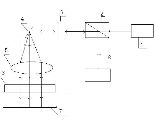
[0011] Specific implementation mode one: according to the instructions attached figure 1 and 2 Specifically illustrate this embodiment, a linear scanning system based on a dual-axis MEMS reflective mirror and an F-Theta lens applied to a laser heterodyne interferometer described in this embodiment, the scanning system includes Laser 1, polarization beam splitting prism 2, 1 / 4 wave plate 3, biaxial MEMS mirror 4, three-piece F-Theta lens group 5, high reflection mirror 6 and photodetector 7, the high reflection mirror 6 The reflectance is 96%~100%, and the biaxial MEMS mirror 4 is located at the focal length of the system of the three-piece F-Theta lens group 5,

[0012] said The output wavelength of laser 1 is The linearly polarized light is sent to a signal receiving end of the polarizing beam splitting prism 2, and the polarizing beam splitting prism 2 transmits the accepted linearly polarized light to output, and the linearly polarized light transmitted through the po...

specific Embodiment approach 2

[0013] Specific implementation mode two: this implementation mode is a further description of specific implementation mode one, in specific implementation mode one The output wavelength of laser 1 is The laser beam diameter of the linearly polarized light is , the area of ​​the effective reflection unit of the dual-axis MEMS mirror 4 is .

specific Embodiment approach 3

[0014] Specific implementation mode three: according to the instructions attached Figure 7 Describe this embodiment in detail. This embodiment is a further description of Embodiment 1 or 2. In the linear scanning system described in Embodiment 1 or 2, the three-piece F-Theta lens group 5 consists of three coaxially arranged The three lenses are composed of lenses, and the three lenses are sequentially: the first lens 5-1 made of SF11, the second lens 5-2 made of SF11, and the third lens 5-3 made of BK7. The system focal length of formula F-Theta lens group 5 is 430mm, and its cylinder length is 280mm, and its front working distance is 242.24mm, and its back working distance is 328.50mm, and described front working distance is the effective of biaxial MEMS mirror 4 The distance between the reflection unit and the first lens 5-1 made of SF11, the rear working distance is the distance between the third lens 5-3 made of BK7 and the object U to be scanned.


PUM


Abstract

The invention discloses a biaxial MEMS reflective galvanometer and F-Theta lens-based linear scanning system used for a laser heterodyne interferometer, which relates to a scanning system using an optical lens and solves the problems that the conventional optical scanning system has single applicable wavelength and cannot realize linear and uniform-speed scanning. The linear scanning system comprises a laser, a polarization beam splitter prism, a 1/4 wave plate, a biaxial MEMS reflective galvanometer, a triplet F-Theta lens set, a high reflection mirror and a photoelectric detector, wherein the biaxial MEMS reflective galvanometer is positioned at the position of a system focal length of the triplet F-Theta lens set. The biaxial MEMS reflective galvanometer and F-Theta lens-based linear scanning system used for the laser heterodyne interferometer is suitable for the scanning system of the laser heterodyne interferometer.

Description

technical field [0001] The invention relates to a scanning system utilizing an optical lens, in particular to a linear scanning system applied to a laser heterodyne interferometer based on a biaxial MEMS reflective vibrating mirror and an F-Theta lens. Background technique [0002] Laser heterodyne interferometer is more and more widely used in semiconductor silicon wafer detection, optical glass production monitoring, and ultra-smooth surface detection process due to its advantages of high measurement accuracy, fast speed, no damage to the sample to be tested, and high sensitivity. However, the scanning measurement of the sample to be tested in the traditional laser heterodyne interferometer achieves the purpose of scanning through the movement of the sample. This scanning method is simple and easy to implement, but it cannot meet the requirements in terms of accuracy. In contrast, fast optical scanning technology has obvious advantages. [0003] Optical scanning technolog...

Claims


Application Information

Patent Timeline
IPC IPC(8): G01B9/02G01N21/01G01N21/45G02B26/10G02B13/00
Inventor 王春晖高龙李彦超丛海芳曲杨
Owner HARBIN INST OF TECH
Why Eureka
Try Eureka