
Ultraviolet radiation comprehensive test device

A comprehensive testing, ultraviolet radiation technology, applied in the field of optical testing, can solve the problems of increasing the attenuation of the ultraviolet optical system, lengthening the focal length of the input optical system, spending huge manpower and material resources, etc., and achieving the effect of reducing attenuation, improving measurement accuracy, and sharing resources

Active Publication Date: 2010-12-15
CHINA NORTH IND NO 205 RES INST
View PDF4 Cites 24 Cited by
  • Summary
  • Abstract
  • Description
  • Claims
  • Application Information

AI Technical Summary

Problems solved by technology

[0011] The advantages and disadvantages of this method are similar to those of the ultraviolet spectral radiance. The test is simple and the operation is convenient. It only needs to replace the ultraviolet standard detector and the ultraviolet measured detector. The disadvantage is that both the input and output optical systems use two mirrors. , the attenuation of the ultraviolet light signal increases, which reduces the signal-to-noise ratio; in addition, due to the need for sufficient space to install the electronic shutter 7 and filter assembly 8, the focal length of the input optical system must be lengthened, thereby increasing the attenuation of the ultraviolet optical system , so that the measurement accuracy is reduced, and the measurement uncertainty of the current ultraviolet spectral responsivity test device is 15%.
[0012] From the above three test devices, it can be seen that the tests of the three parameters have common parts: UV standard light source, UV monochromator, output optical system, UV Standard detectors and data processing systems, etc., if the application unit establishes three corresponding independent test devices at the same time to complete the measurement of the above three parameters, it will take huge manpower and material resources

Method used


Image

  • Ultraviolet radiation comprehensive test device
  • Ultraviolet radiation comprehensive test device
  • Ultraviolet radiation comprehensive test device

Examples


Embodiment Construction

[0026] The present invention will be further described in detail below in conjunction with the accompanying drawings and preferred embodiments.

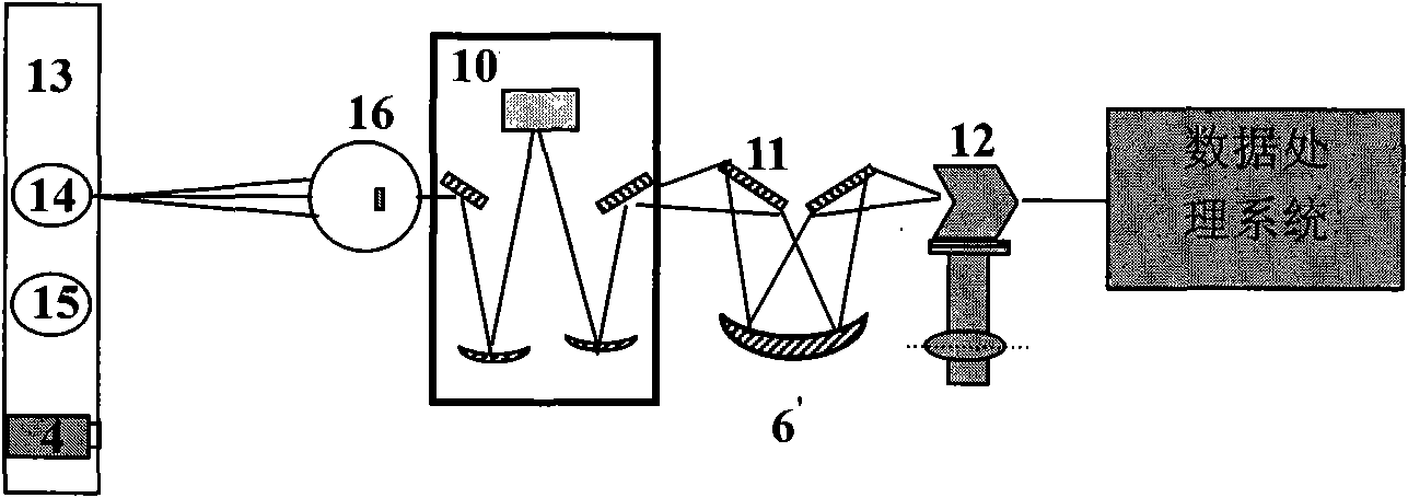
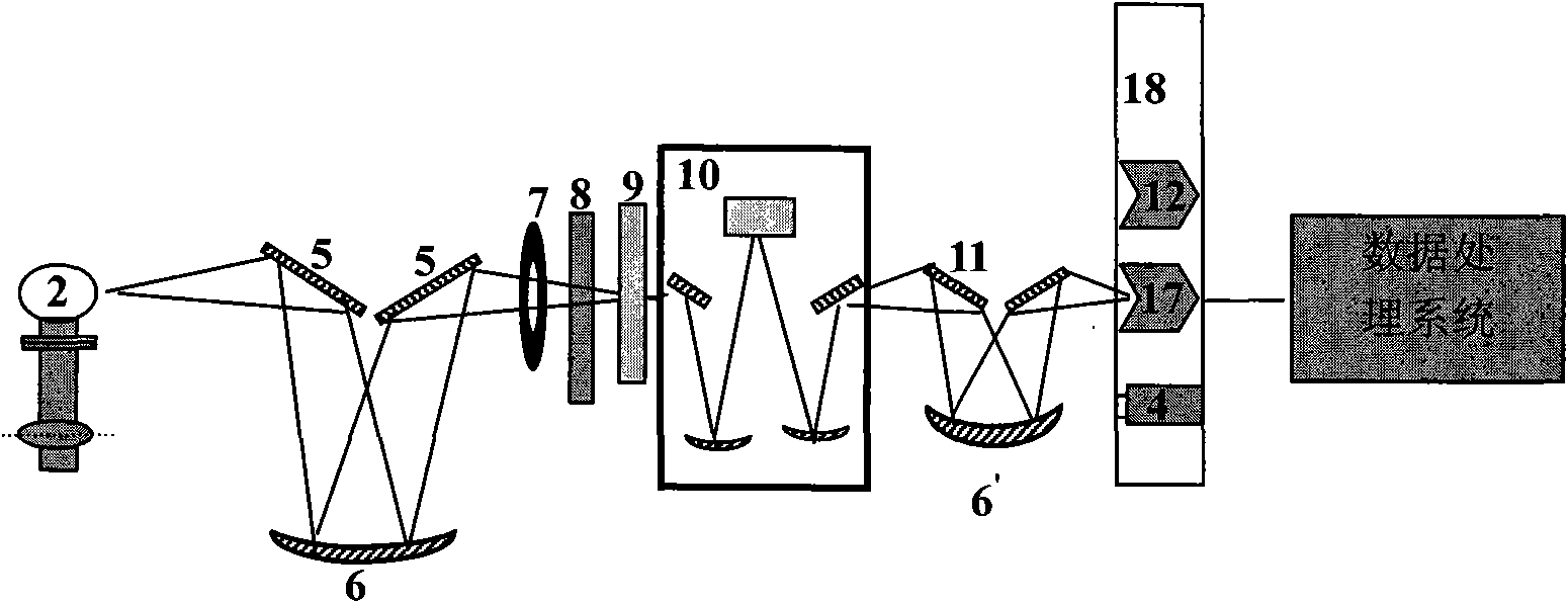
[0027] according to Figure 4As shown, the preferred embodiment of the ultraviolet radiation comprehensive testing device of the present invention includes a light source assembly, an input optical system, a multifunctional filter assembly 8, a chopper 9, an ultraviolet monochromator, an output optical system, an ultraviolet detector assembly, and a data processing system , can complete the multi-parameter test of UV spectral radiance, UV spectral irradiance and UV spectral responsivity.

[0028] The chopper 9, UV monochromator and output optics are all prior art. The ultraviolet monochromator 10 contains a wavelength controller, and the ultraviolet monochromator 10 is located in the optical path between the multifunctional filter assembly 6 and the output optical system. The chopper 9 contains a modulation disc and a motor. The bl...


PUM


Abstract

The invention discloses an ultraviolet radiation comprehensive test device and belongs to the field of optical tests and measurements. The device simplifies an input optical system, adds an integrating sphere and an ultraviolet irradiance standard lamp which is arranged on a second mobile platform, and correspondingly integrates the integrating sphere and an electronic shutter on a first mobile platform with the ultraviolet radiance standard lamp and a filtering component on the basis of a conventional spectral responsivity test device; the first mobile platform is in the same direction as a third mobile platform with an ultraviolet standard detector and is vertical to the second mobile platform; and all the standard lamps or the standard detector and lamps to be measured or detectors to be measured are cut into a measurement optical path under control of a data processing system so as to realize measurement and calibration of ultraviolet spectral radiance, spectral radiance illuminance and spectral responsivity. The device solves the problems of resource sharing and cost saving during ultraviolet radiation measurement, and has the characteristics of simple operation and high precision.

Description

technical field [0001] The invention belongs to the field of optical testing, and mainly relates to an ultraviolet radiation testing device, in particular to an ultraviolet radiation comprehensive testing device capable of measuring three parameters of ultraviolet spectrum radiance, ultraviolet spectrum irradiance and ultraviolet spectrum responsivity. Background technique [0002] UV spectral radiance, UV spectral irradiance and UV spectral responsivity are the three basic parameters in the field of UV radiation testing. The following methods are usually used to test the above parameters respectively. [0003] (1) UV spectrum radiance test device [0004] The test of the radiance of ultraviolet spectrum is generally completed by comparing the standard lamp and the lamp under test. Its test system such as figure 1 As shown, it mainly consists of a UV radiance standard lamp 2, a UV radiance measured lamp 3, a one-dimensional mobile platform 1, an input optical system contai...

Claims


Application Information

Patent Timeline
IPC IPC(8): G01J3/00G01J1/00G01J1/04G01J3/02
Inventor 占春连陈超李正琪卢飞李燕刘建平刘瑜
Owner CHINA NORTH IND NO 205 RES INST
Learn More