Process for smelting ultra clean steel by single-nozzle refining furnace

A single-nozzle refining furnace, ultra-clean technology, applied in the field of iron and steel metallurgy, can solve the problems of prolonging refining time, low desulfurization efficiency, shortening the life of refractory materials, etc., achieving excellent refining efficiency, low content of non-metallic inclusions, and fine particles Effect

Inactive Publication Date: 2010-12-22
UNIV OF SCI & TECH BEIJING
View PDF4 Cites 27 Cited by
  • Summary
  • Abstract
  • Description
  • Claims
  • Application Information

AI Technical Summary

Problems solved by technology

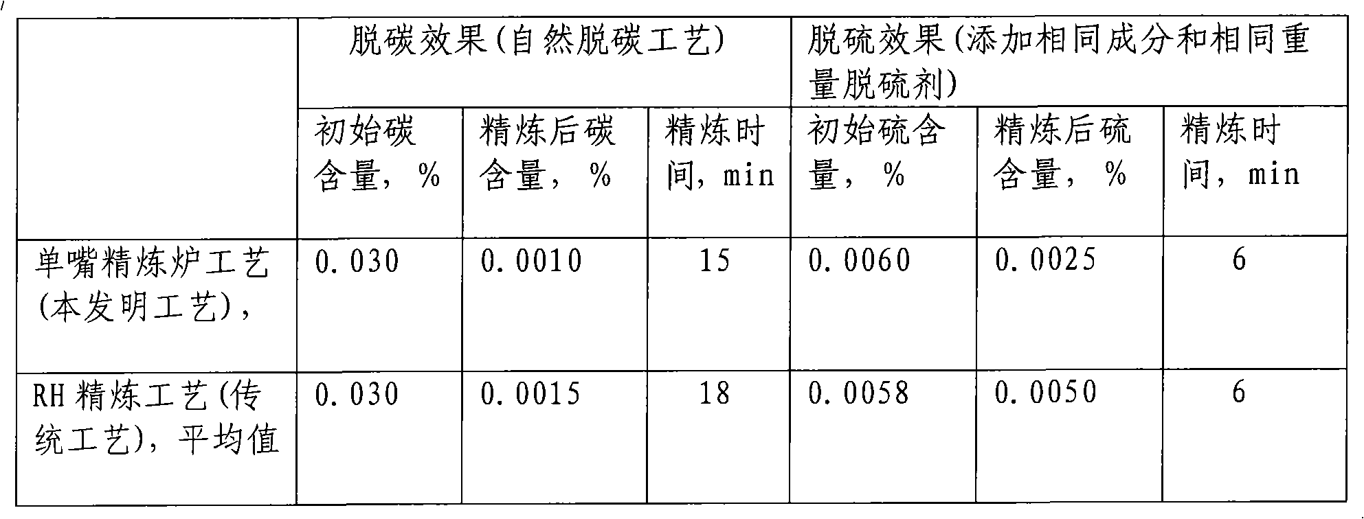
[0004] 1. In terms of smelting ultra-low carbon steel, the production of high-end automotive steel plates and other products requires molten steel with lower carbon content, and the RH refining furnace can only take measures such as prolonging the refining time to reduce the final carbon content, but this will inevitably reduce production efficiency
[0005] 2. In terms of refining desulfurization, the RH refining furnace is limited by its own liquid steel circulation characteristics, which makes the desulfurization efficiency low in the refining process; although in actual production, the vacuum chamber is used to add granular desulfurizers, top gun injection desulfurization powder and other processes , but the effect is not ideal, and adding too much desulfurizer will significantly reduce the life of the refractory
Chinese patent application 200910272881.1 discloses "A Method for Smelting Low-Sulphur Steel Using a Single Nozzle Refining Furnace", but this patent only involves the desulfurization process of molten steel, and does not include the removal process of carbon, nitrogen, hydrogen, oxygen and inclusions

Method used


Image

  • Process for smelting ultra clean steel by single-nozzle refining furnace
  • Process for smelting ultra clean steel by single-nozzle refining furnace
  • Process for smelting ultra clean steel by single-nozzle refining furnace

Examples


Embodiment 1

[0061] Converter + single nozzle refining furnace + slab continuous casting process is adopted to smelt ultra-low carbon clean steel by vacuum natural decarburization process.

[0062] The steel is tapped from the converter to the single nozzle refining furnace; molten steel conditions: 100 tons of steel tapping, 0.03% carbon content, 0.08% oxygen content, temperature 1630°C, slag thickness 70mm; free space above the ladle slag surface 500mm, ladle slag Composition: CaO 45%, SiO2 20%, MgO 8%, Al 2 o 3 3%, Fe t O 19%, CaF 2 2%, other residues are not more than 3%.

[0063] When the ladle reaches the single-nozzle refining furnace station, blow argon gas from the bottom of the ladle, control the blowing flow rate to 450NL / min, blow off the slag covered on the surface of the ladle as far as possible, and then insert the suction nozzle into the ladle to a depth of 350mm below the surface, vacuum treatment is carried out as follows:

[0064] The vacuum natural decarburizatio...

Embodiment 2

[0074] Converter + single nozzle refining furnace + slab continuous casting process is adopted to smelt ultra-low carbon clean steel by vacuum forced decarburization process.

[0075] In this embodiment, the process steps are substantially the same as in Embodiment 1, and only the differences are described below, and the similarities are not repeated;

[0076]Conditions of molten steel: carbon content 0.045%, oxygen content 0.04%, temperature 1610°C, slag thickness 50mm; free space above ladle slag surface 500mm, ladle slag composition: CaO 46%, SiO 2 22%, MgO 8%, Al 2 o 3 3%, Fe t O 18%, other residues not more than 3%.

[0077] Insert the suction nozzle into the ladle to a depth of 330mm below the liquid steel surface, and carry out vacuum treatment as follows:

[0078] Using the forced decarburization process, within 3 minutes after the start of vacuum treatment, reduce the pressure in the vacuum chamber to 6KPa, and then start blowing oxygen with the oxygen blowing f...

Embodiment 3

[0082] Converter + single nozzle refining furnace + slab continuous casting process is adopted to smelt ultra-low carbon clean steel with temperature control process.

[0083] In this embodiment, the process steps are substantially the same as in Embodiment 1, and only the differences are described below, and the similarities are not repeated;

[0084] Conditions of molten steel: carbon content 0.03%, oxygen content 0.08%, temperature 1570°C, slag thickness 50mm; free space above ladle slag surface 500mm, ladle slag composition: CaO 46%, SiO 2 22%, MgO 8%, Al 2 o 3 3%, Fe t O 18%, other residues not more than 3%.

[0085] Insert the suction nozzle into the ladle to a depth of 300mm below the liquid steel surface, and carry out vacuum treatment as follows:

[0086] Temperature rise Within 3 minutes after the start of the vacuum treatment, reduce the pressure in the vacuum chamber to 6KPa, then add 200Kg of metal aluminum, and start blowing oxygen with the oxygen blowing f...


PUM

PropertyMeasurementUnit
sizeaaaaaaaaaa

Abstract

The invention discloses a process for smelting ultra clean steel by a single-nozzle refining furnace, belonging to the technical field of ferrous metallurgy. The process comprises the followings steps of: blowing in argon gas from the bottom of steel ladle with the blowing gas flow quantity of 1-10 NL / min per ton of steel, and inserting a suction nozzle into the steel ladle; carrying out a vacuum natural decarburization technology when the initial carbon content in liquid steel is smaller than 0.035%, and carrying out a vacuum forced decarburization technology when the initial carbon content in the liquid steel is greater than 0.035%, wherein the time for decarburization is 12-22 min; after decarburization, maintaining the pressure of a vacuum chamber to be les than 100-200 Pa, adding 1-6 kg of deoxidizer per ton of steel, and adding 0.5-8 kg of desulfurizer per ton of steel in 1-2 min after the deoxidizer is added, wherein the flow quantity of argon gas is 1-10 NL / min per ton of steel, and the time for desulfurization is 5-15 min; and deoxidizing and removing impurities after desulfurization. The process can simultaneously reduce the content of impurity elements comprising carbon, sulfur, nitrogen, hydrogen and oxygen and impurities in the liquid steel to an extremely low level within limited refining time, and the refining efficiency is obviously superior to that of an RH refining furnace.

Description

technical field [0001] The invention relates to an ultra-clean steel smelting process, in particular to a process for smelting ultra-clean steel using a single nozzle refining furnace, which belongs to the technical field of iron and steel metallurgy. Background technique [0002] In the field of steelmaking technology, removing impurity elements in steel to the greatest extent and obtaining high-quality, high-performance ultra-clean steel has always been the most concerned research topic for steelmakers. As the main means of secondary refining of molten steel, the extra-furnace refining technology has been widely recognized and successfully applied at home and abroad, and vacuum refining is the most representative component of the extra-furnace refining technology. At present, the most commonly used device for vacuum refining of molten steel is the RH (Rheinstahl Heraeus process, circular degassing method) refining furnace, which can not only remove carbon, sulfur, oxygen, ...

Claims


Application Information

Patent Timeline
Patent Type & Authority Applications(China)
IPC IPC(8): C21C7/10C21C7/068C21C7/06C21C7/064
Inventor 张鉴成国光秦哲
Owner UNIV OF SCI & TECH BEIJING
Why Eureka
Try Eureka