

Organic dye and photoelectric conversion device with same
A photoelectric conversion device and organic dye technology, applied in organic dyes, photovoltaic power generation, azo dyes, etc., can solve the problems of organic dyes without dye-sensitized solar cells, low stability, durability, conversion efficiency, etc., to reduce LUMO The energy level, the energy gap of the dye is narrowed, and the effect of reducing energy loss
Active Publication Date: 2010-12-29
IND TECH RES INST
View PDF7 Cites 10 Cited by
- Summary
- Abstract
- Description
- Claims
- Application Information
AI Technical Summary
Problems solved by technology
However, due to low stability, durability, and conversion efficiency, there are currently no organic dyes available for practical application in dye-sensitized solar cells (DSSCs).
Method used
View moreImage
Smart ImageViewing Examples

Examples
preparation example Construction
Embodiment 1
Embodiment 5
Login to View More PUM
 Abstract
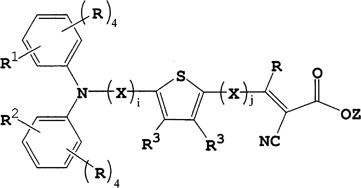
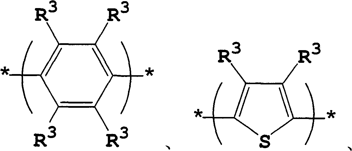
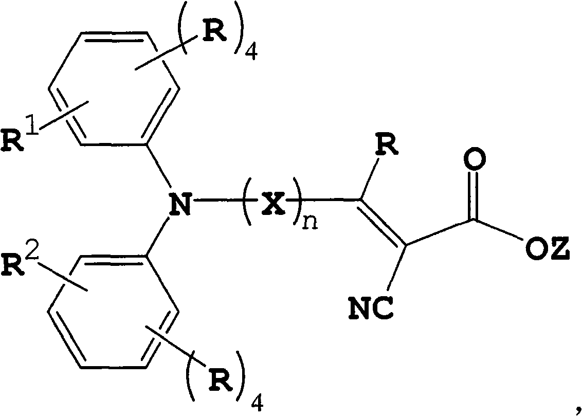
The invention provides an organic dye and a photoelectric conversion device with the same. The organic dye has a structure shown in the specification, wherein n is an integer from 3 to 11; a plurality of Xes are independent respectively and are selected from groups consisting of the following components and combinations thereof; R is respectively independent H, halogen atoms, C1 to C18 alkyl, C1 to C18 alkoxy, C3 to C18 heterocyclic alkyl, C3 to C20 aryl, C3 to C20 heterocyclic aryl, C3 to C20 alcyl or C3 to C20 cycloalkyl; R1 and R2 are respectively independent the H, the halogen atoms, the C1 to C18 alkyl, the C1 to C18 alkoxy, the C3 to C18 heterocyclic alkyl, the C3 to C20 aryl, the C3 to C20 heterocyclic aryl, the C3 to C20 alcyl or the C3 to C20 cycloalkyl, or the R1 is connected with the R2 to form a loop with 5 to 14 elements; R3 is respectively independent the H, the halogen atoms, nitryl, amido, the C1 to C18 alkyl, the C1 to C18 alkoxy, C1 to C18 alkyl sulfide, the C3 to C18 heterocyclic alkyl, the C3 to C20 aryl, the C3 to C20 heterocyclic alkyl, the C3 to C20 alcyl or the C3 to C20 cycloalkyl; and Z is hydrogen, alkali metal or quaternary ammonium salt.
Description
technical field The invention relates to an organic dye, in particular to an organic dye used in a photoelectric conversion device. Background technique In response to the need for energy conservation, various alternative renewable energy sources have been explored. In recent years, Gratzel and O'Regan proposed a dye-sensitized solar cell (dye-sensitized solar cell, DSSC), which can more effectively utilize solar energy, which has attracted a lot of attention in the industry. In general, the structure of a dye-sensitized solar cell includes four parts, which are the cathode / anode electrode that provides the current flow path, the semiconductor titanium dioxide (TiO 2 ), a dye layer, and an electrolyte for transporting holes. The material of each part of the above-mentioned dye-sensitized solar cell and the interface structure between each part will affect the efficiency of the module, and the dye in the dye layer is the most important factor affecting the efficiency of the...
Claims
Login to View More Application Information
Patent Timeline
 Patent Type & AuthorityApplications(China)
IPC IPC(8): C09B57/00H01L51/42H01L51/46H01L51/50H01L51/54H01G9/20
CPCY02E10/542Y02E10/549
Inventor童永梁吴佳音陈壬安徐心怡吴春桂钟旻峰蔡松雨
OwnerIND TECH RES INST