Sequential simulated moving bed
A simulated moving bed, sequential technology, applied in the direction of chemical instruments and methods, separation methods, solid adsorbent liquid separation, etc., can solve the problems that the equipment cannot operate automatically, cannot switch working modes, etc., to avoid poor circulation, avoid The effect of blockage of circulation and avoidance of accumulation
- Summary
- Abstract
- Description
- Claims
- Application Information
AI Technical Summary
Problems solved by technology
Method used
Image
Examples
Embodiment 1
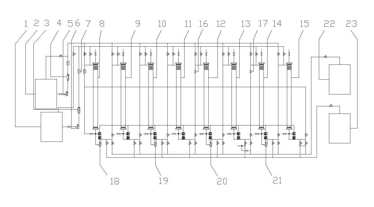
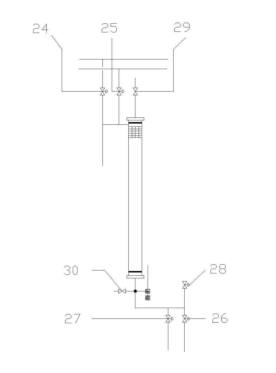
[0022] When the 8-column system is running, open the V-column manual valve 16 and VII-column manual valve 17. Start the raw material pump 5 and the washing water pump 6, and at the same time, the automatic control system controls the I column feed valve 24, the V column water inlet valve 25, the VI column extract liquid outlet valve 26, the III column raffinate outlet valve 27, and the I column circulation pneumatic valve 28. Pneumatic valve 28 for column II circulation and pneumatic valve 28 for column V are opened, and the rest of the valves are closed. At this time, No. I chromatographic column 8 feeds material, and the feed flow rate is 14 L / H. No. II chromatographic column 9 enters water for elution. It is 13L / H, the outlet of No. III chromatographic column 10 exits the raffinate, enters the raffinate tank 23, the exit of No. VI chromatographic column 13 exits the extract, enters the extract tank 22, the feeding time and eluent feeding time are 300S Finally, the raw mater...
Embodiment 2
[0026] When the 4-column system is running, the automatic control system closes the manual valve 16 of the column V and the manual valve 17 of the column VII. Start the raw material pump 5 and the washing water pump 6, the automatic control system controls the I column feed valve 24, the III column water inlet valve 25, the III column extract liquid outlet valve 26, the I column raffinate outlet valve 27 to open, and the other valves to close. When No. I chromatographic column 8 feeds, No. III chromatographic column 10 enters water for elution, the outlet of No. I chromatographic column 8 exits the raffinate, enters the raffinate tank 23, and No. III chromatographic column 10 exits the extract solution, enters the extraction The liquid tank 22, the feeding time, the eluent feeding time and the switch of the pneumatic valve before and after this step are controlled by the automatic control system. Then, the raw material pump 5 and the washing water pump 6 are closed, and the au...
Embodiment 3
[0029] Before the 6-column system runs, first, the automatic control system opens the V-column manual valve 16, closes the VII-column manual valve 17, and switches the 4-column system into a 6-column system. When the system is running, at first, start the raw material pump 5 and the washing water pump 6, and the automatic control system controls the I column feed valve 24, the V column water inlet valve 25, the V column extract liquid outlet valve 26, the II column raffinate outlet valve 27, I column circulation pneumatic valve 28 is opened, and other valves are closed. At this time, No. I chromatographic column 8 feeds material, V No. chromatographic column 12 enters water for elution, and No. II chromatographic column 9 exits the raffinate, which enters the raffinate tank 23 , No. Ⅴ chromatographic column 12 exits extracting liquid, enters extracting liquid tank 22, feed time, enter eluent time and the switch of pneumatic valve before and after this step are controlled by com...
PUM
 Abstract
Description
Claims
Application Information
 - R&D
- Intellectual Property
- Life Sciences
- Materials
- Tech Scout
- Unparalleled Data Quality
- Higher Quality Content
- 60% Fewer Hallucinations
Browse by: Latest US Patents, China's latest patents, Technical Efficacy Thesaurus, Application Domain, Technology Topic, Popular Technical Reports.
© 2025 PatSnap. All rights reserved.Legal|Privacy policy|Modern Slavery Act Transparency Statement|Sitemap|About US| Contact US: help@patsnap.com


