
Operation method of ozonizer and ozonizer apparatus used therefor

An ozone generating device and ozone technology, which are applied in the directions of oxygen/ozone/oxide/hydroxide, ozone preparation, chemical instruments and methods, etc., can solve problems such as the reduction of ozone generation capacity, and achieve the effect of ensuring safety

Inactive Publication Date: 2011-01-12
CHLORINE ENGINEERS CORP LTD
View PDF1 Cites 14 Cited by
  • Summary
  • Abstract
  • Description
  • Claims
  • Application Information

AI Technical Summary

Problems solved by technology

For example, lead dioxide (PbO 2 ) of the electrolytic ozone generator, if the ozone generator is stopped without providing a protective current, the following problems will arise: the reduction caused by the hydrogen generated from the cathode passing through the cation exchange membrane to the anode, or the hydrogen gas passing through the anode constituent material The reduction reaction of the local battery formed by the contact causes lead dioxide to be reduced to lead oxide (PbO) or lead (Pb) which has almost no ozone generating ability and conductivity, or reduced to lead ions and dissolved in the solution , which in turn leads to the problem that the ozone generation ability of the anode is reduced

Method used


Image

  • Operation method of ozonizer and ozonizer apparatus used therefor
  • Operation method of ozonizer and ozonizer apparatus used therefor
  • Operation method of ozonizer and ozonizer apparatus used therefor

Examples


Embodiment 1

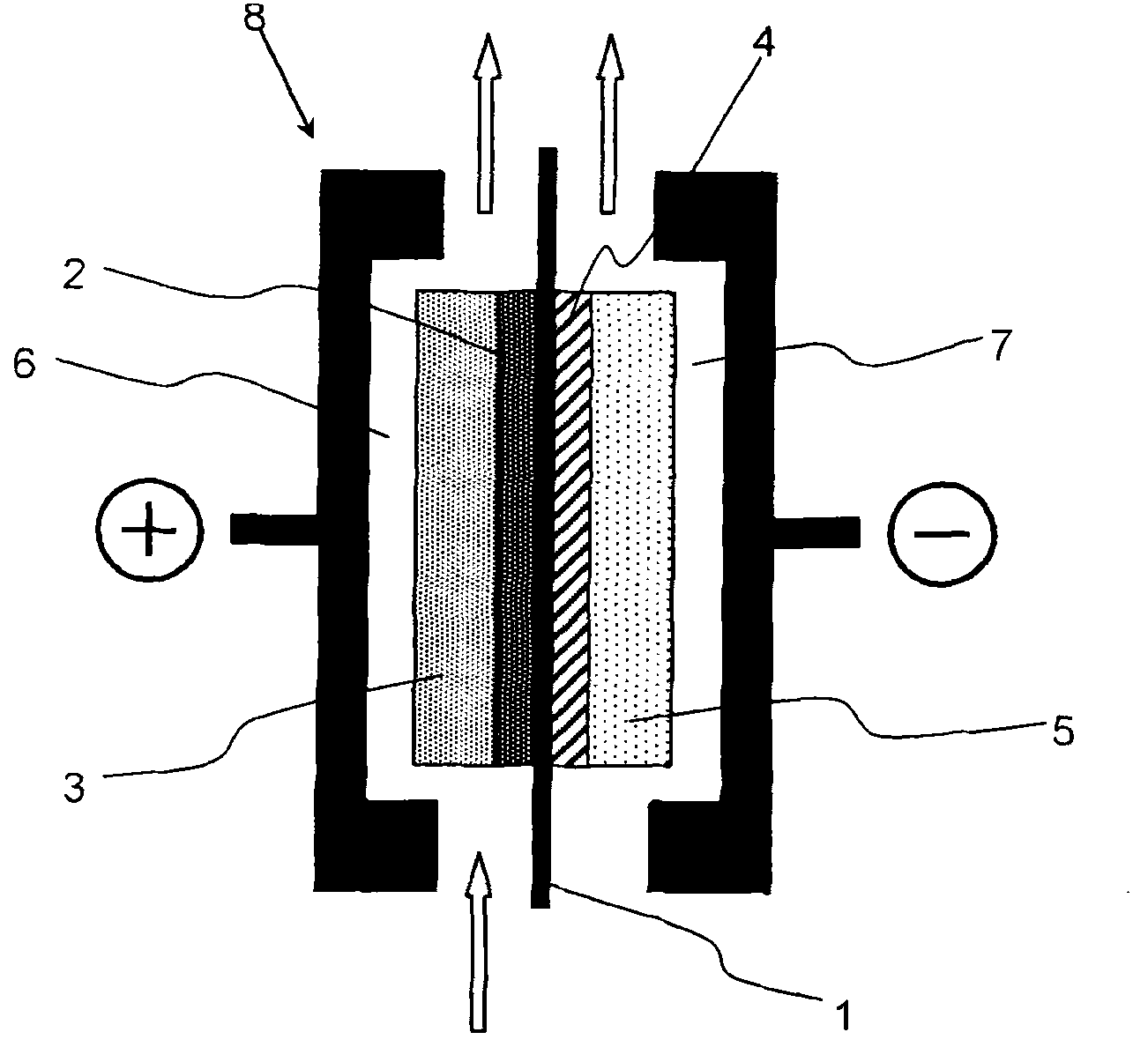
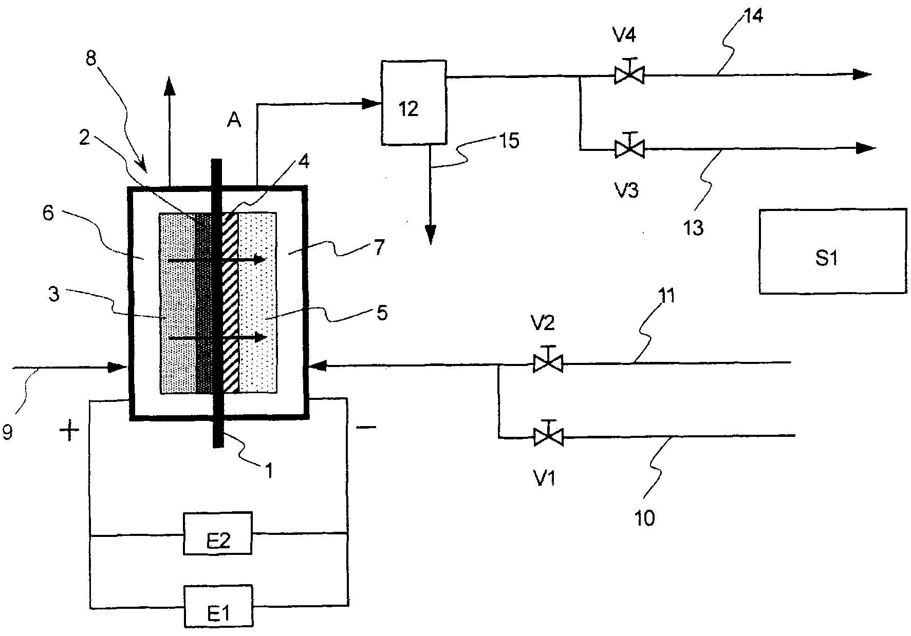
[0092] Use a neutral detergent on a 1mm thick titanium vibrating fiber sintered body (びび made by Chitan 繊 After cleaning and degreasing the junction, Tokyo Steel Co., Ltd., pickled it with 20% by mass, 50°C hydrochloric acid solution for 1 minute to perform pretreatment, and then used the thermal decomposition method on the vibrating fiber made of titanium. A cladding layer containing platinum-titanium-tantalum (25-60-15 mol%) is formed on the sintered body, thereby producing an anode current collector or anode base 3 with an undercoat layer formed on the surface.

[0093] With the anode current collector or anode substrate 3 as the anode and 400g / l lead nitrate aqueous solution as the electrolyte, at 60°C, 1A / dm 2 The electrolysis was carried out for 60 minutes under certain conditions, thereby forming the anode 2 on the surface of the anode current collector or the anode substrate 3, the anode 2 comprising a coating layer of the anode catalyst, ie, β-lead dioxide.

[009...

Embodiment 2

[0100] After carrying out normal electrolysis according to the same operation as in Example 1, switch to the protection current, replace the electrolyzed water and gas in the cathode chamber with pure water, and after the replacement, supply oxygen concentrated through PSA to the cathode chamber at a speed of 0.3 L / min ( When the oxygen concentration was 96%), no hydrogen concentration was detected in the anode generated gas, and no hydrogen concentration was detected in the cathode chamber exhaust gas. The battery voltage is 0.4V.

Embodiment 3

[0102] After carrying out normal electrolysis according to the same operation as in Example 1, switch to the protection current, and use an air pump to supply air to the cathode chamber at a speed of 0.5 L / min. At this time, the water in the cathode chamber is discharged, and there is no Hydrogen concentration was detected and was not detected in the cathode chamber exhaust gas. The battery voltage is 0.5V.


PUM

PropertyMeasurementUnit
thicknessaaaaaaaaaa
porosityaaaaaaaaaa

Abstract

The present invention offers an operation method of an ozonizer and an ozonizer apparatus to improve ozone gas purity and to achieve long and safety electrolysis operation in such manner that, during normal operation of the ozonizer, ozone gas is generated at the anode in the anode compartment and hydrogen gas is generated at the cathode in the cathode compartment; and only when the ozonizer is stopped and operation is switched to protective current operation during which minute electric current is supplied to protect said anode, oxygen-containing gas is supplied to said cathode compartment after electrolyte and hydrogen gas in said cathode compartment are all drained out, so that said cathode is made function as a gas electrode for oxygen reduction reaction, using said cathode as a reversible electrode with two functions as a gas generation electrode and a gas electrode, thereby during normal operation, ozone is generated efficiently, and during the protective current operation, when safety is a key issue, hydrogen gas is not generated at the cathode and mingling of hydrogen gas into ozone gas generated at the anode is prevented.

Description

technical field [0001] The present invention relates to an ozone generating device, which electrolyzes water by making the anode and the cathode close to the two sides of a solid polymer electrolyte diaphragm made of a cation exchange membrane, thereby generating ozone at the anode and generating hydrogen at the cathode . In addition, the present invention relates to an operating method of an ozone generating device and an ozone generating device. Using the ozone generating device and its operating method, it is possible to suppress the hydrogen gas generated at the cathode from penetrating through the cation exchange membrane to the anode. The purity of the anode gas discharged from the electrolytic cell is reduced under the action of the protective current that is turned on when the ozone generator stops operating, so as to achieve long-term safe operation. Background technique [0002] The electrolysis device formed by making the anode and the cathode tightly bonded to b...

Claims


Application Information

Patent Timeline
Patent Type & Authority Applications(China)
IPC IPC(8): C25B1/13C25B1/10C25B9/23
CPCC01B2201/62H01M4/8605C25B15/02C01B2201/32C01B13/115C01B2201/12C01B2201/24C01B2201/22C25B1/13C25B9/10C01B2201/34Y02E60/366Y02E60/50C25B9/23C01B13/10Y02E60/36
Inventor 加藤昌明川口理惠
Owner CHLORINE ENGINEERS CORP LTD
Learn More