Method for recycling low-temperature waste heat from waste incineration fume

A technology of waste incineration and low-temperature waste heat, which is applied to the low-temperature waste heat recovery and utilization of flue gas in the chemical industry, iron and steel, and low-temperature waste heat recovery and utilization of waste incineration flue gas. Waste and other problems, to achieve good development prospects and promotion value, low operating costs, strong acid resistance

Inactive Publication Date: 2011-01-26
TIANJIN TEDA ENVIRONMENTAL PROTECTION +1
View PDF4 Cites 3 Cited by
  • Summary
  • Abstract
  • Description
  • Claims
  • Application Information

AI Technical Summary

Problems solved by technology

After waste incineration, the moisture content of the flue gas exceeds 30%, and the temperature reaches above 150°C, so the water vapor is directly discharged. Not only the physical sensible heat of the flue gas is not utilized, but also the latent heat of vaporization is wasted, and thick white smoke will be formed in winter , a nuisance to the surrounding residents

Method used


Image

  • Method for recycling low-temperature waste heat from waste incineration fume
  • Method for recycling low-temperature waste heat from waste incineration fume
  • Method for recycling low-temperature waste heat from waste incineration fume

Examples


Embodiment 1

[0019] Low temperature flue gas conditions after dedusting: temperature 150°C, dust content about 2g / Nm 3 , the flow is about 92881Nm 3 / h, moisture content 31%.

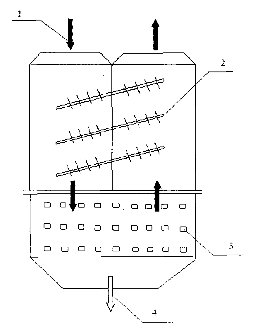
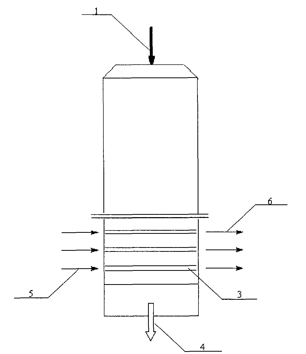
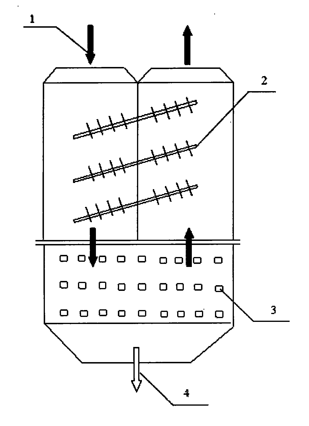
[0020] The low-temperature flue gas 1 after dedusting flows through the whole system in a U shape. On the inlet side, the flue gas 1 is first cooled by the heat pipe 2 to recover part of the sensible heat, and the temperature is reduced to 120°C, and then enters the shell side of the tube condenser 3 to reduce the flue gas temperature below the dew point temperature, about 34°C. The normal temperature cooling water 5 in the tube side is heated accordingly to obtain hot water 6 . In this process, the total waste heat recovery can reach 13MW, and the flue gas condensate 4 is discharged from the bottom of the equipment. On the outlet side, the low-temperature flue gas recovers the sensible heat of the flue gas 1 on the inlet side through the heat pipe 2, and then the temperature rises again, reaching 80°C, and final...

Embodiment 2

[0023] Low temperature flue gas conditions after dedusting: temperature 160°C, dust content about 1.5g / Nm 3 , the flow is about 113456Nm 3 / h, moisture content 22%.

[0024] The low-temperature flue gas 1 after dedusting flows through the whole system in a U shape. On the inlet side, the flue gas 1 first cools down through the heat pipe 2 and recovers part of the sensible heat, the temperature drops to 135°C, and then enters the shell side of the tube condenser 3 to reduce the flue gas temperature below the dew point temperature, about 50°C. The normal temperature cooling water 5 in the tube side is heated accordingly to obtain hot water 6 . In this process, the total waste heat recovery can reach 10MW, and the flue gas condensate 4 is discharged from the bottom of the equipment. On the outlet side, the low-temperature flue gas recovers the sensible heat of the flue gas 1 on the inlet side through the heat pipe 2, and then the temperature rises again, reaching 90°C, and fin...

Embodiment 3

[0027] Low temperature flue gas conditions after dedusting: temperature 180°C, dust content about 1.8g / Nm 3 , the flow is about 10762Nm 3 / h, moisture content 25%.

[0028] The low-temperature flue gas 1 after dedusting flows through the whole system in a U shape. On the inlet side, the flue gas 1 first cools down through the heat pipe and recovers part of the sensible heat, the temperature drops to 130°C, and then enters the shell side of the tube condenser 3 to lower the flue gas temperature below the dew point temperature, about 59°C. The normal temperature cooling water 5 in the tube side is heated accordingly to obtain hot water 6 . In this process, the total waste heat recovery can reach 8MW, and the flue gas condensate 4 is discharged from the bottom of the equipment. On the outlet side, the low-temperature flue gas recovers the sensible heat of the flue gas 1 on the inlet side through the heat pipe 2, and then the temperature rises again, reaching 85°C, and finally ...


PUM


Abstract

The invention relates to a method for recycling low-temperature waste heat from waste incineration fume. The method comprises the following steps of: (1) introducing dedusted low-temperature waste incineration fume into a cold end of a heat pipe type heat exchanger to cool, wherein a heat-conducting medium in a heat pipe is gasified and enters a hot end of the heat pipe at the same time, and fume contact sides of the heat pipe type heat exchanger are coated with an anticorrosive material; (2) introducing the cooled fume into a shell pass of a shell and tube condenser and fully exchanging the heat between the cooled fume and room temperature water in a tube pass to recycle the waste heat, wherein the fume contact sides of the shell and tube condenser are coated with the anticorrosive material; (3) collecting fume condensed fluid under the action of gravity on the lower part of the condenser to discharge, and performing subsequent innocent treatment; (4) introducing the condensed fume into the hot end of the heat pipe type heat exchanger to heat, wherein the heat conducting medium in the heat pipe is condensed and is returned to the cold end of the heat pipe in a gravity flow mode for repeated heat exchange at the same time; and (5) introducing the heated fume into a chimney to discharge directly. The method has the advantages of simple process, compact structure, small occupied area, small investment, low operating cost and the like, and thus has wide development prospect and high popularization value.

Description

technical field [0001] The invention relates to a method for recovering low-temperature waste heat of flue gas, in particular to the recovery and utilization of low-temperature waste heat of waste incineration flue gas, and is also applicable to the recovery and utilization of low-temperature waste heat of flue gas in fields such as iron and steel and chemical industry under the same conditions. Background technique [0002] Municipal solid waste, crop stalks, and municipal sludge are produced in a large amount and have a wide range of influences, which have become one of the important factors that seriously restrict the healthy development of my country's society and economy. At present, the national municipal solid waste production is as high as 160 million tons per year, and it is increasing at a rate of 5%-8% year by year. The incineration technology to deal with municipal solid waste is gradually rising in China due to its advantages of minimizing the amount of waste, m...

Claims


Application Information

Patent Timeline
Patent Type & Authority Applications(China)
IPC IPC(8): F23G5/46F28F19/02
Inventor 韩檬张曙光高建东郝永俊赵昕哲闫志海徐朝阳董珂董楠
Owner TIANJIN TEDA ENVIRONMENTAL PROTECTION
Why Eureka
Try Eureka