Carbon nano-tube manufacturing method and carbon nano-tube manufacturing apparatus

A carbon nanotube and a manufacturing method technology, applied in the field of carbon nanotube manufacturing devices, can solve the problems of high carbon nanotubes, unusable, difficult to control the height of catalysts, etc.

Inactive Publication Date: 2011-01-26
HITACHI CHEM CO LTD
View PDF13 Cites 24 Cited by
  • Summary
  • Abstract
  • Description
  • Claims
  • Application Information

AI Technical Summary

Problems solved by technology

Since the continuous supply of these three gases is the premise, there is no need to mention the switching operation of the gas.
In addition, in the method of Patent Document 1, the catalyst is attached to the carbon nanotubes, so impurities are mixed into the product.
In addition, according to the method of Patent Document 1, the carbon precipitates remaining in the fluidized bed cannot be removed, and the carbon precipitates will accumulate
As a result, until more carbon nanotubes are obtained, the particles of the fluidization medium are covered with carbon and cannot be used.
[0027] Thus, in the conventional fluidized bed production method, it is impossible to produce high-purity carbon nanotubes
Also, low productivity
Catalyst height control is difficult due to simultaneous carbon nanotube synthesis and catalyst loading

Method used


Image

  • Carbon nano-tube manufacturing method and carbon nano-tube manufacturing apparatus
  • Carbon nano-tube manufacturing method and carbon nano-tube manufacturing apparatus
  • Carbon nano-tube manufacturing method and carbon nano-tube manufacturing apparatus

Examples


Embodiment 1

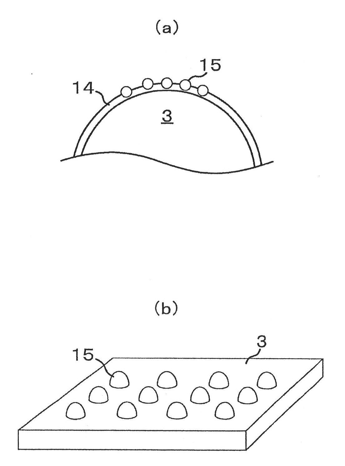
[0164] Example 1 of the present invention will be described. Here, as a support, alumina beads are used, on which Al 2 o 3 . Al 2 o 3 The carrier was sputtered into a film on alumina beads. The alumina beads had a diameter of 0.5 mm. Al 2 o 3 The thickness of the carrier (carrier layer) was 20 nm. Moreover, in Al 2 o 3 Fe is supported on the carrier as a catalyst. This loading is carried out by sputtering. Loaded on Al 2 o 3 The thickness of Fe on the support was 1 nm. Put this support in the reactor, while supplying 60Torr C to the reactor 2 h 4 / 200TorrH 2 / 100ppmvH 2 Carbon nanotubes are synthesized in a fluidized bed state while using atmospheric pressure gas of O / Ar balance.

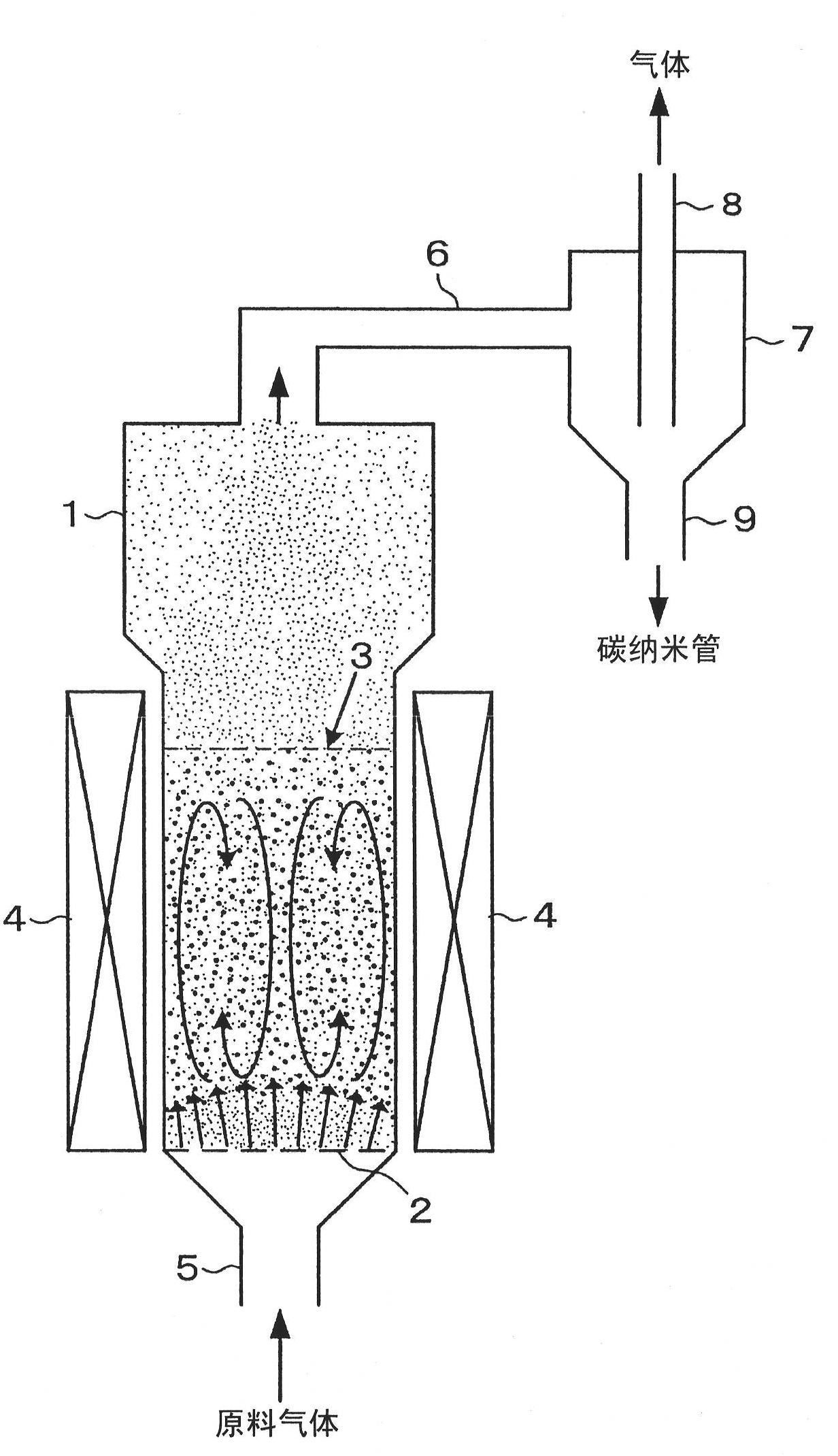
[0165] The reactor is Figure 5 The shown quartz glass is a vertical CVD reactor that can be used both as a fixed bed and as a fluid bed. The temperature of the reaction part in the reactor was 800°C. The supply of normal-pressure gas was performed for 10 minutes, and the synth...

Embodiment 2

[0174] Next, Embodiment 2 of the present invention will be described. In Example 2, the catalyst was supported by circulating the carrier raw material vapor and the catalyst raw material vapor over the alumina beads in a high temperature state. Thereafter, carbon source steam was circulated over the catalyst-loaded high-temperature alumina beads to synthesize carbon nanotubes. Here, alumina beads were used as the support. As the alumina beads, those having a diameter of 0.5 mm were used. In this example 2, in Figure 4 Alumina beads were installed in the shown horizontal CVD apparatus, and the following processes were performed.

[0175] First, 0.2 to 0.5 mL of tetraethoxyorthosilicate (TEOS) was supplied under normal pressure with the entire apparatus heated to about 700°C. The TEOS supplied into the reactor evaporates and reacts on the surface of the alumina beads to form SiO 2 carrier layer. Next, set the device as a whole to about 400°C, and use SiO 2 Coated alumina...

Embodiment 3

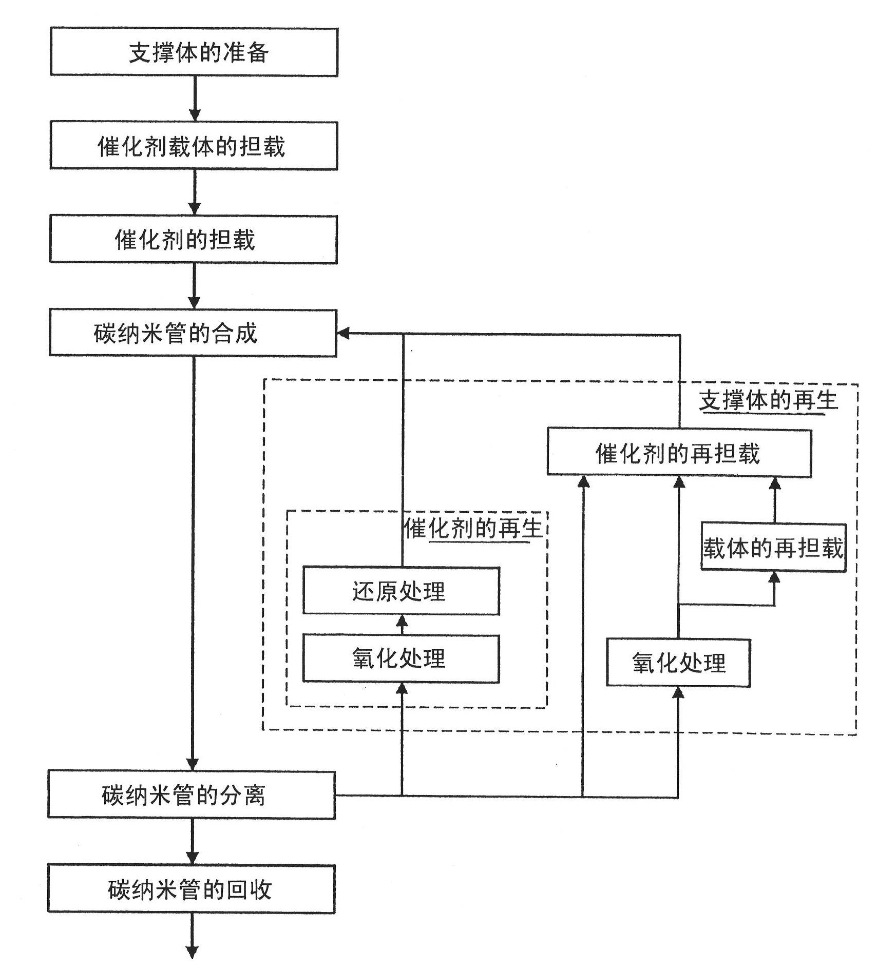
[0178] Next, Embodiment 3 of the present invention will be described. In Example 3, the synthesis of carbon nanotubes was repeated. Here, as the support, alumina beads with a diameter of 0.5 mm were used. In this embodiment 3, in Figure 4 Alumina beads were installed in the horizontal CVD apparatus shown, and the following treatments were performed. First, SiO is formed on the surface of the alumina beads 2 carrier layer. Specifically, after heating the entire reaction apparatus to about 700° C., 0.2 to 0.5 mL of TEOS was supplied onto the alumina beads under normal pressure. The TEOS supplied into the reactor evaporates and reacts on the surface of the alumina beads to form SiO 2 carrier layer.

[0179] made of SiO 2 Coated alumina beads are loaded with Al at the same time 2 o 3 Support and Fe catalyst. This simultaneous loading is performed after heating the entire reaction apparatus to about 400°C. Simultaneously supply 3 mg of aluminum isopropoxide vapor as car...


PUM

PropertyMeasurementUnit
diameteraaaaaaaaaa
thicknessaaaaaaaaaa
diameteraaaaaaaaaa

Abstract

The carbon nano-tube manufacturing method disclosed in the present invention is a carbon nano-tube manufacturing method that uses a carbon source that contains carbon and is pyrolyzed in a heated state, and a catalyst used for generating carbon nano-tubes from said carbon source to synthesize said carbon nano-tubes on a heated support arranged in a reactor. This method is characterized by the following facts: it has a catalyst loading step wherein said catalyst is loaded on said support by circulating the raw material of said catalyst on said support, a synthesis step wherein said carbon nano-tubes are synthesized on said support by circulating said carbon source on said support, and a separation step wherein said carbon nano-tubes are separated from said support by circulating a separation gas flow on said support; said catalyst loading step, synthesis step, and separation step are carried out while switching said catalyst raw material, carbon source, and separation gas flows with said support kept in said heated state.

Description

technical field [0001] The present invention relates to a method for manufacturing carbon nanotubes and a device for manufacturing carbon nanotubes. More specifically, the present invention relates to a production method for mass-producing carbon nanotubes having various structures at low cost and on a large scale, and a carbon nanotube production apparatus used in the production method. Background technique [0002] Carbon nanotubes are materials having a rolled graphene sheet structure and a one-dimensional structure with a very large aspect ratio (see Non-Patent Document 1). It is known that carbon nanotubes have excellent mechanical strength and flexibility; have semiconductor or metal conductivity; and also have very stable chemical properties. As methods for producing carbon nanotubes, arc discharge method, laser evaporation method, and chemical vapor growth method (hereinafter referred to as CVD (Chemical Vapor Deposition) method) have been reported. In particular, ...

Claims


Application Information

Patent Timeline
Patent Type & Authority Applications(China)
IPC IPC(8): C01B31/02B01J23/745
CPCB01J8/1836B01J37/0209C01B2202/04B01J37/0221B01J8/0055B82Y40/00B01J37/0238B01J2208/00407B01J8/34C01B31/0226B01J23/745B01J23/28B01J37/347B01J37/0217B01J37/0244B01J23/70B82Y30/00C01B32/16B82B3/0004B82B3/0009C01B32/162
Inventor 野田优杉目恒志山口由岐夫大泽利男笕和宪长谷川馨金东荣
Owner HITACHI CHEM CO LTD
Why Eureka
Try Eureka