Manufacturing method of surface adhered light-emitting element lamp group

A surface-adhesive, light-emitting element technology is applied in the field of process design of semiconductor light-emitting element lamp sets to achieve the effects of saving man-hours, precise positioning, and increasing efficiency

Inactive Publication Date: 2011-02-02
RUBERNOS
View PDF2 Cites 1 Cited by
  • Summary
  • Abstract
  • Description
  • Claims
  • Application Information

AI Technical Summary

Problems solved by technology

[0007] The main purpose of the present invention is to provide a method for manufacturing a surface-mounted light-emitting element lamp group, which is very easy in assembly and construction, to quickly and reliably manufacture a surface-mounted light-emitting element lamp group, and to solve the production problems of the known technology

Method used


Image

  • Manufacturing method of surface adhered light-emitting element lamp group
  • Manufacturing method of surface adhered light-emitting element lamp group
  • Manufacturing method of surface adhered light-emitting element lamp group

Examples


Embodiment Construction

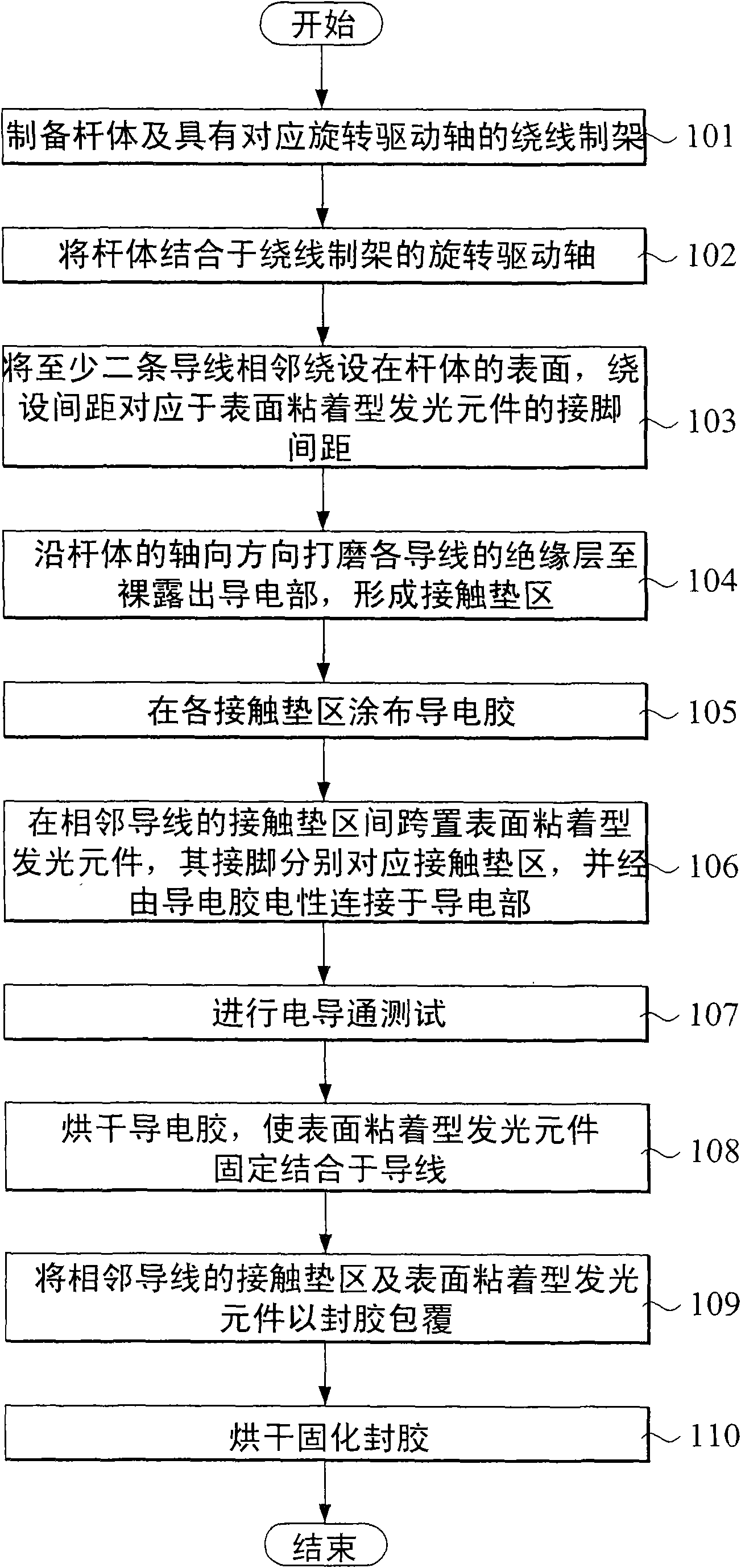
[0052] The specific embodiments adopted by the present invention will be further described through the following embodiments and accompanying drawings.

[0053] refer to figure 1 As shown, it is a flow chart showing the steps of the preferred embodiment of the present invention, and at the same time coordinates Figure 2 to Figure 12 A description of the preferred embodiments of the present invention is as follows.

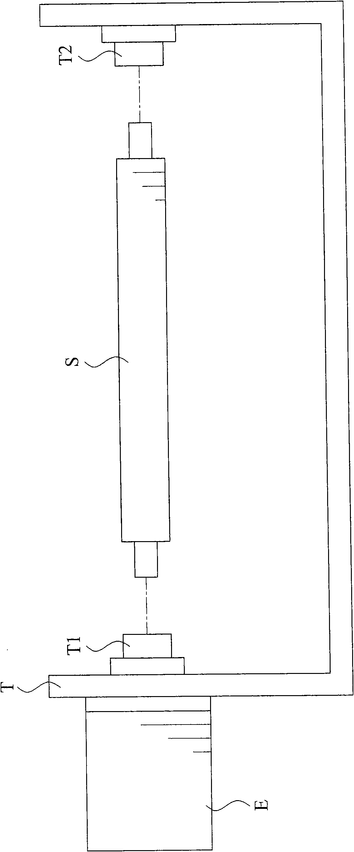
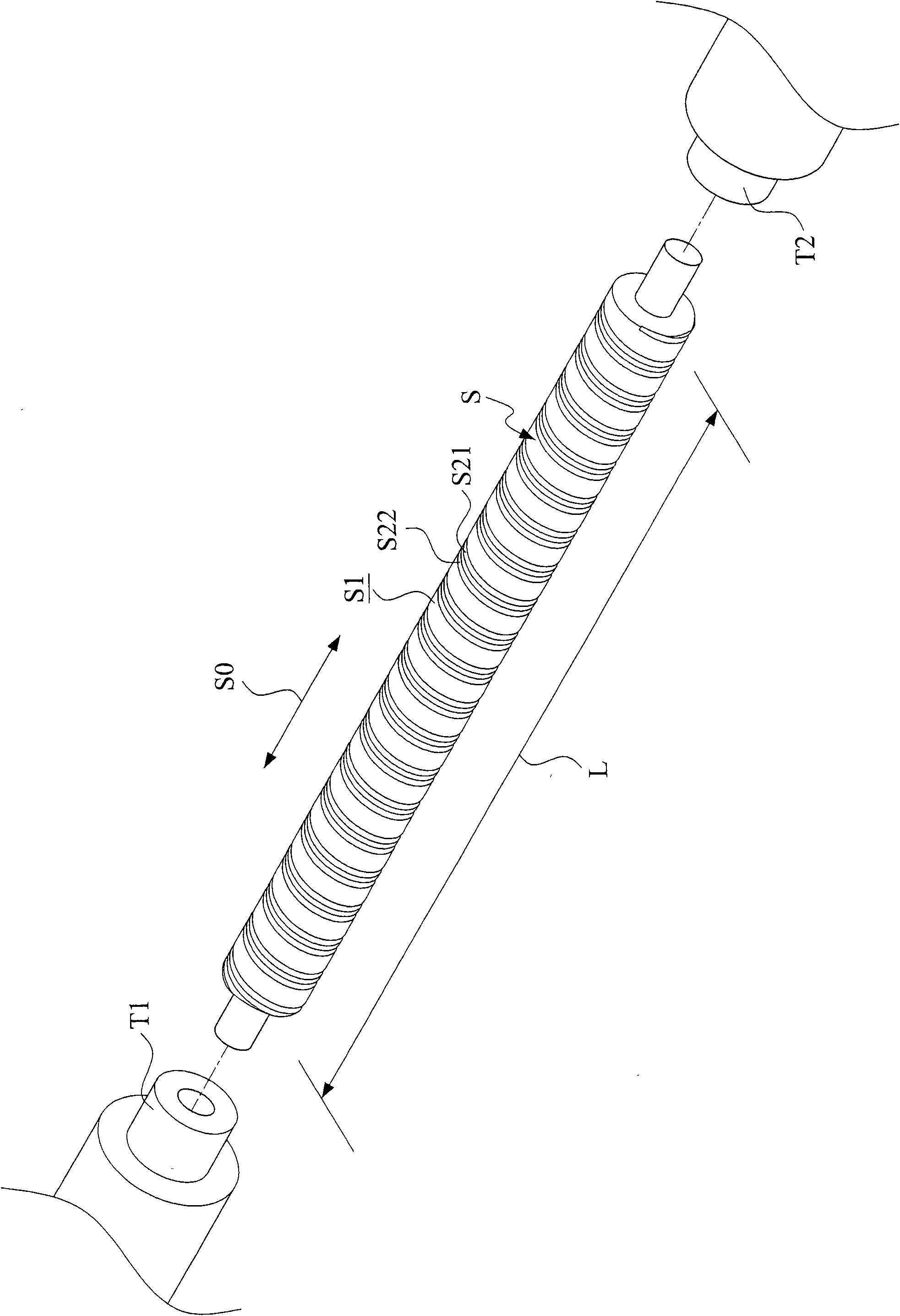
[0054] refer to figure 2 , image 3 and Figure 4 , first prepare a rod S with a predetermined length L and a winding frame T with corresponding rotating drive shafts T1, T2 (step 101). Then the rod S is combined with the rotating drive shafts T1 and T2 of the winding frame T, and the rotating driving shafts T1 and T2 are driven to rotate by a winding device E (step 102 ).

[0055] refer to Figure 5 When at least two wires 1, 2 with outer covering insulating layers 11, 21 are arranged at a predetermined winding distance D, when the rod body S is driven to ...


PUM


Abstract

The invention discloses a manufacturing method of a surface adhered light-emitting element lamp group, which comprises the following steps of: firstly, manufacturing a rod with a predetermined length and a winding frame with a corresponding rotary drive shaft; driving the rod to rotate by using a winding device after integrating the rod with the rotary drive shaft so as to wind conducting wires around the surface of the rod adjacently in a predetermined winding distance, wherein the winding distance is corresponding to the pin distance of a selected surface adhered light-emitting element; polishing an insulating layer of each conducting wire along the axial direction of the rod until the conducting part of each conducting wire is exposed, forming contact pad regions, coating a conducting adhesive to each contact pad region, bridging the surface adhered light-emitting element so that all pins of the surface adhered light-emitting element are respectively corresponding to the contact pad regions of the adjacent conducting wires; and electrically connecting the pins with the conducting parts of the conducting wires through the conducting adhesive, and coating with a sealing adhesive.

Description

technical field [0001] The invention relates to a manufacturing process design of a semiconductor light-emitting element lamp set, in particular to a manufacturing method of a surface-mounted light-emitting element lamp set. Background technique [0002] In recent years, semiconductor light-emitting elements have gradually replaced general traditional lighting equipment. Taking Light Emitting Diode (LED) as an example, it has the advantages of small size, fast response, long life, not easy to attenuate, solid appearance, shock resistance, full-color light (including invisible light), easy pointing design, low voltage, Low current, low conversion loss, small heat radiation, easy mass production, environmental protection and other advantages. [0003] The known structure of the LED is formed by wrapping an LED chip with a light bulb-shaped encapsulant. A pair of pins extend from the LED chip, and pass through the encapsulant for electrical connection. When in use, a pair of ...

Claims


Application Information

Patent Timeline
Patent Type & Authority Applications(China)
IPC IPC(8): F21V23/00F21S4/00F21V21/002F21Y101/02F21Y115/10
Inventor 蔡乃成
Owner RUBERNOS
Why Eureka
Try Eureka