High thermal conductivity resin composition and high thermal conductivity coated metal foil board manufactured by using same

A resin composition and high thermal conductivity technology, applied in the fields of high thermal conductivity metal-clad laminates and high thermal conductivity resin compositions, can solve the problems of no processability, low glass transition temperature, low heat resistance, etc., and achieve good flexibility properties and tensile strength, meeting high thermal conductivity requirements, and the effect of excellent high thermal conductivity

Active Publication Date: 2011-02-16
GUANGDONG SHENGYI SCI TECH
View PDF6 Cites 56 Cited by
  • Summary
  • Abstract
  • Description
  • Claims
  • Application Information

AI Technical Summary

Problems solved by technology

[0006] This patent uses this curing agent to cure epoxy resin as the matrix of high thermal conductivity materials. Although the curing agent improves heat resistance and adhesion, the compatibility between the curing agent and epoxy resin is not good , easy to precipitate during use, and the process performance is poor, especially in the highly filled filler system.
Patent CN101343402 discloses a method of high thermal conductivity prepreg, but because of the lack of toughness in the resin system used, the prepared non-glass fiber reinforced thermal conductive adhesive film has poor flexibility, especially when filled with a large amount of thermal conductive filler Finally, it is very brittle, easy to break and crack during use, and does not have good processability
The high thermal conductivity adhesive film prepared by JP 2003-140047 is based on (meth)acrylic compound as the main resin, filled with thermal conductive fillers such as alumina, although the adhesive film prepared by this method has good flexibility, the glass transition temperature If it is too low, it is -65°C, which is not suitable for the application of high thermal conductivity copper clad laminates
Moreover, the existing high thermal conductivity adhesive films often have problems such as low heat resistance, insufficient flexibility, weak adhesion to copper foil, and low thermal conductivity.

Method used


Image

  • High thermal conductivity resin composition and high thermal conductivity coated metal foil board manufactured by using same
  • High thermal conductivity resin composition and high thermal conductivity coated metal foil board manufactured by using same
  • High thermal conductivity resin composition and high thermal conductivity coated metal foil board manufactured by using same

Examples


Embodiment 1

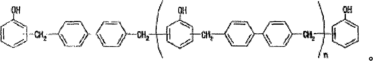
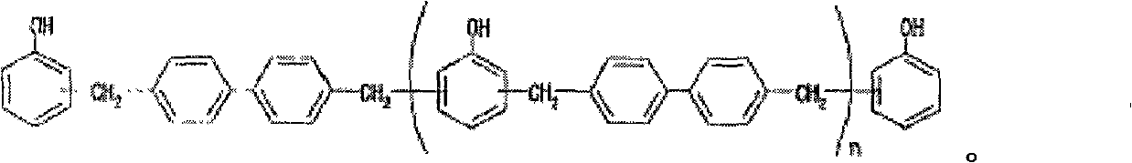
[0063]Add the following resins in sequence in a clean container: brominated epoxy resin 100g, then add carboxy-terminated nitrile rubber 253g, first stir the above resin for about 30min, after mixing evenly, add biphenyl type phenolic resin curing agent ( Solid content 50%) 92.2g, and curing accelerator 2-MI 0.05g, continue to stir and mix for 1h to obtain pure resin glue (solid content is 40%), and then use the glue to coat, and the coating carrier adopts 35μm thick copper foil. After the coating is completed, bake the sheet in an oven at 110°C for 1.5 minutes to semi-cure to form a resin-composite copper foil, then take two sheets of the prepared resin-composite copper foil and laminate them with their glued sides, at 190°C for 90 minutes, carry out Pressing at high temperature results in a high thermal conductivity copper clad laminate.

Embodiment 2

[0065] Add 40g of solvent MC to a clean container, then add 113g of alumina, continue to stir for about half an hour, add 50g of the glue solution configured in Example 1, continue to stir for half an hour, and then disperse through a high-shear emulsifier, disperse The time is 0.5 hours. Coating is carried out after uniform dispersion, and the coating carrier adopts copper foil with a thickness of 35 μm. After the coating is completed, bake the sheet in an oven at 110°C for 1.5 minutes to semi-cure to form a resin-composite copper foil, then take two sheets of the prepared resin-composite copper foil and laminate them with their glued sides, at 190°C for 90 minutes, carry out Pressing at high temperature results in a high thermal conductivity copper clad laminate.

Embodiment 3

[0067] Add 48g of solvent MC to a clean container, then add 90g of alumina, continue to stir for about 10min, then add 23g of boron nitride, continue to stir for 10min, add 50g of the glue solution prepared in Example 1, and continue to stir for half an hour , and then dispersed through a high-shear emulsifier, and the dispersion time was 0.5 hours. Apply after uniform dispersion. Coating carrier adopts 35μm thick copper foil. After the coating is completed, bake the sheet in an oven at 110°C for 1.5 minutes to semi-cure to form a resin-composite copper foil, then take two sheets of the prepared resin-composite copper foil and laminate them with their glued sides, at 190°C for 90 minutes, carry out Pressing at high temperature results in a high thermal conductivity copper clad laminate.


PUM

PropertyMeasurementUnit
thicknessaaaaaaaaaa
thicknessaaaaaaaaaa

Abstract

The invention relates to a high thermal conductivity resin composition and a high thermal conductivity coated metal foil board manufactured by using the same. The high thermal conductivity resin composition comprises the following components of: epoxy resin, at least one phenoxy resin or carboxy terminal butadiene acrylonitrile, biphenyl phenolic resin and a high thermal conductivity packing material, wherein the biphenyl phenolic resin has the structure shown in the specification. The high thermal conductivity coated metal foil board manufactured by using the high thermal conductivity resin composition comprises a high thermal conductivity adhesive film and metal foils coated on both sides of the high thermal conductivity adhesive film, wherein the high thermal conductivity adhesive film comprises a carrier film and the high thermal conductivity resin composition coated on the carrier film, and the carrier film is a polyester film or a polyimide film. The high thermal conductivity coated metal foil board comprises a resin composite metal foil and a metal foil or another resin composite metal foil coated on the previous resin composite metal foil, and the resin composite metal foil comprises a metal foil and the high thermal conductivity resin composition coated on the metal foil.

Description

technical field [0001] The invention relates to a resin composition, in particular to a high thermal conductivity resin composition and a high thermal conductivity metal foil-clad board made of the resin composition. Background technique [0002] With the development of electronic products in the direction of lightness, thinness, shortness, smallness, high density, and multi-function, the assembly density and integration of components on the circuit board are getting higher and higher, and the heat dissipation requirements of the substrate are becoming more and more urgent. . In the traditional circuit board structure, due to the small number and power consumption of electronic components inserted on it, the heat generated by the electronic components can be dissipated through the copper foil layer on the circuit board, and the heat can be dissipated directly into the air. Convection controls the temperature of electronic components. Although the current circuit boards do n...

Claims


Application Information

Patent Timeline
Patent Type & Authority Applications(China)
IPC IPC(8): C08L71/10C08L63/10C08K3/34B32B15/08C08K9/04C08K3/22C08K3/38C08K3/28C08L61/06C08L63/02C08K9/06C08L13/00C08L79/08C08L63/00
Inventor 苏民社孔凡旺
Owner GUANGDONG SHENGYI SCI TECH
Why Eureka
Try Eureka