Diesel injector coupler applied to multiple fuels

A diesel engine and fuel injector technology, applied in fuel injection devices, engine components, machines/engines, etc., can solve problems such as seizure, achieve the effects of preventing leakage, reducing processing costs, and simplifying processing technology

Inactive Publication Date: 2011-03-16
CHANGZHOU YITONG FUEL EJECTOR MFG
View PDF1 Cites 6 Cited by
  • Summary
  • Abstract
  • Description
  • Claims
  • Application Information

AI Technical Summary

Problems solved by technology

However, when the diesel injector assembly is working, there must be good lubrication conditions between the needle valve and the needle valve body, otherwise it is easy to cause seizure, because the viscosity of dimethyl ether, methanol, and ethanol is higher t

Method used


Image

  • Diesel injector coupler applied to multiple fuels
  • Diesel injector coupler applied to multiple fuels
  • Diesel injector coupler applied to multiple fuels

Examples


Embodiment 1

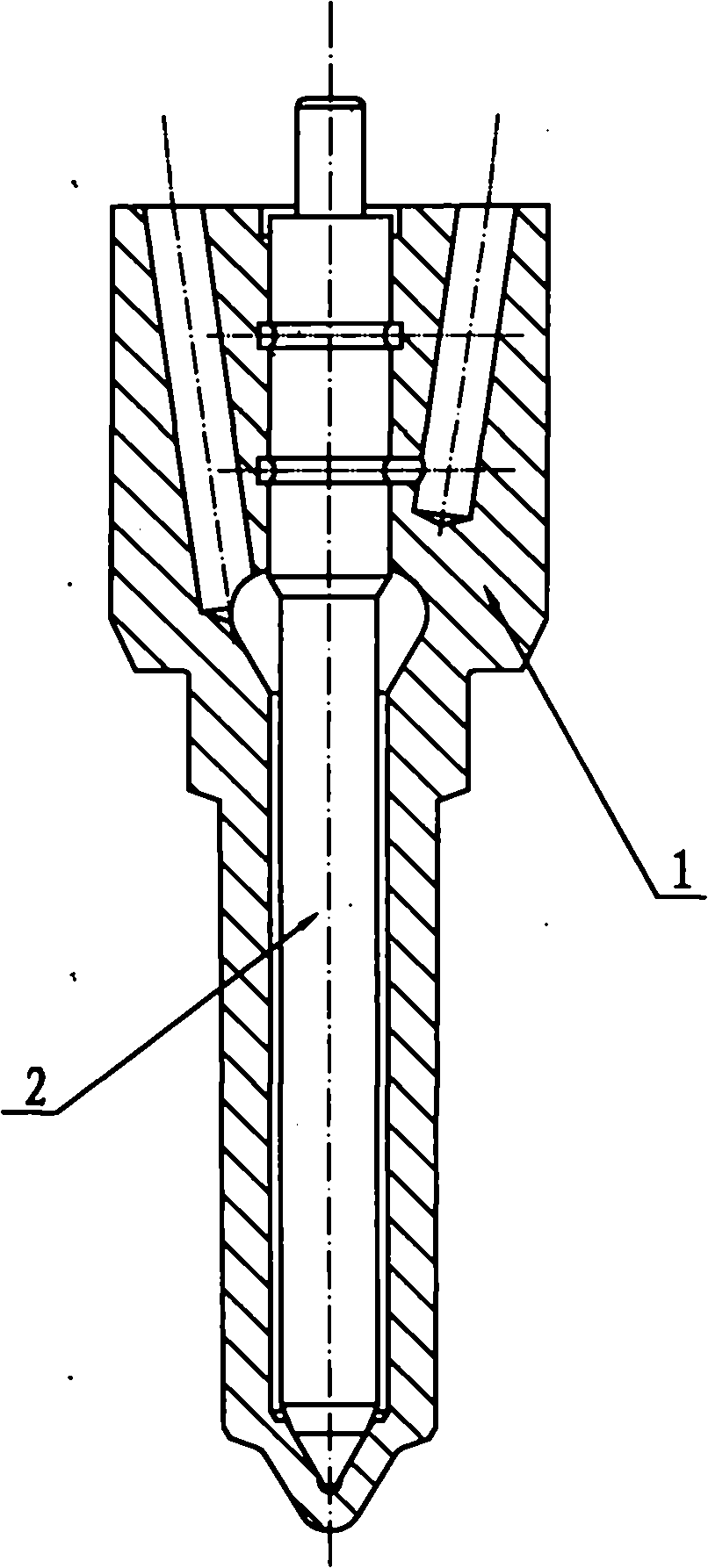
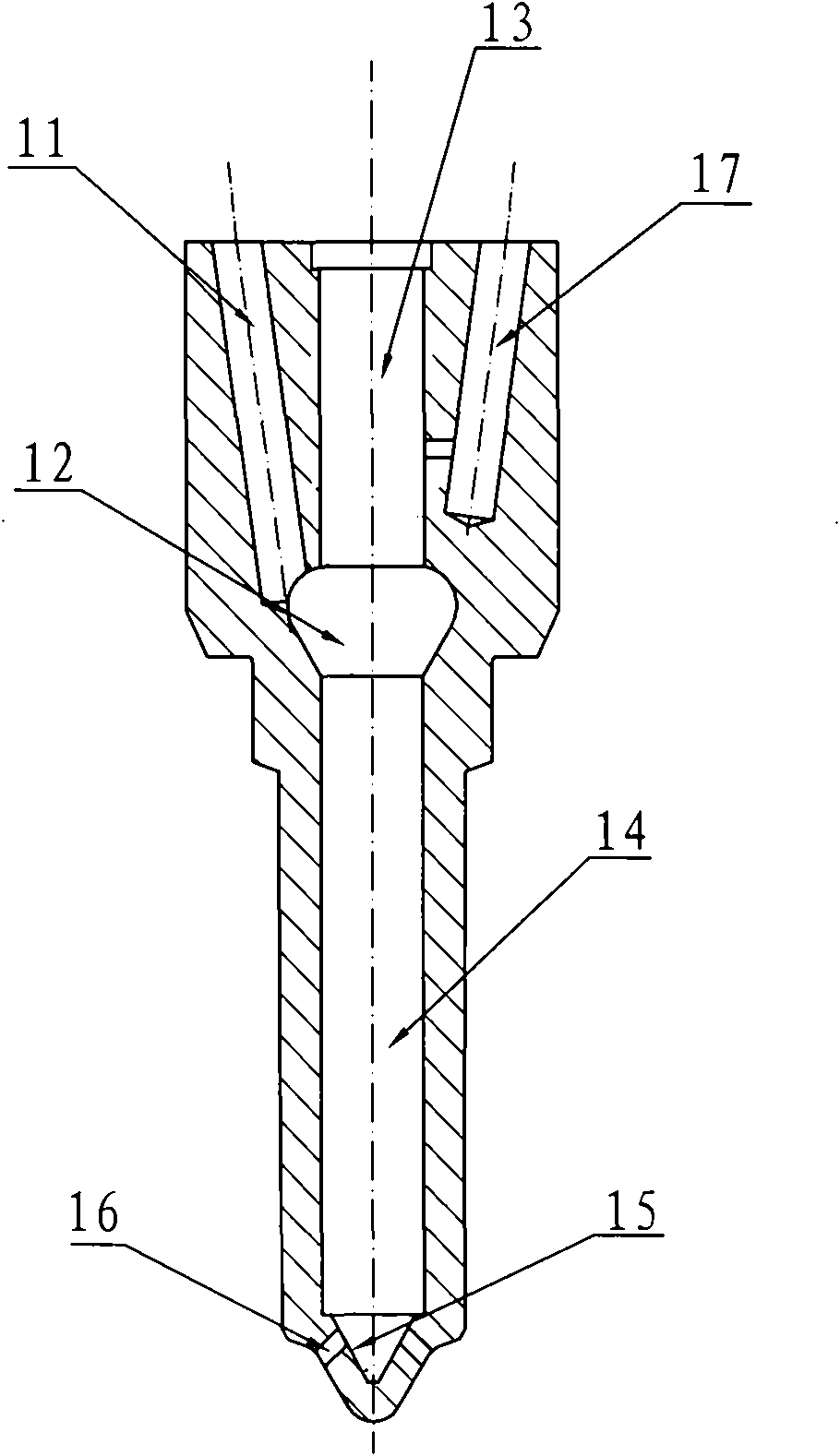
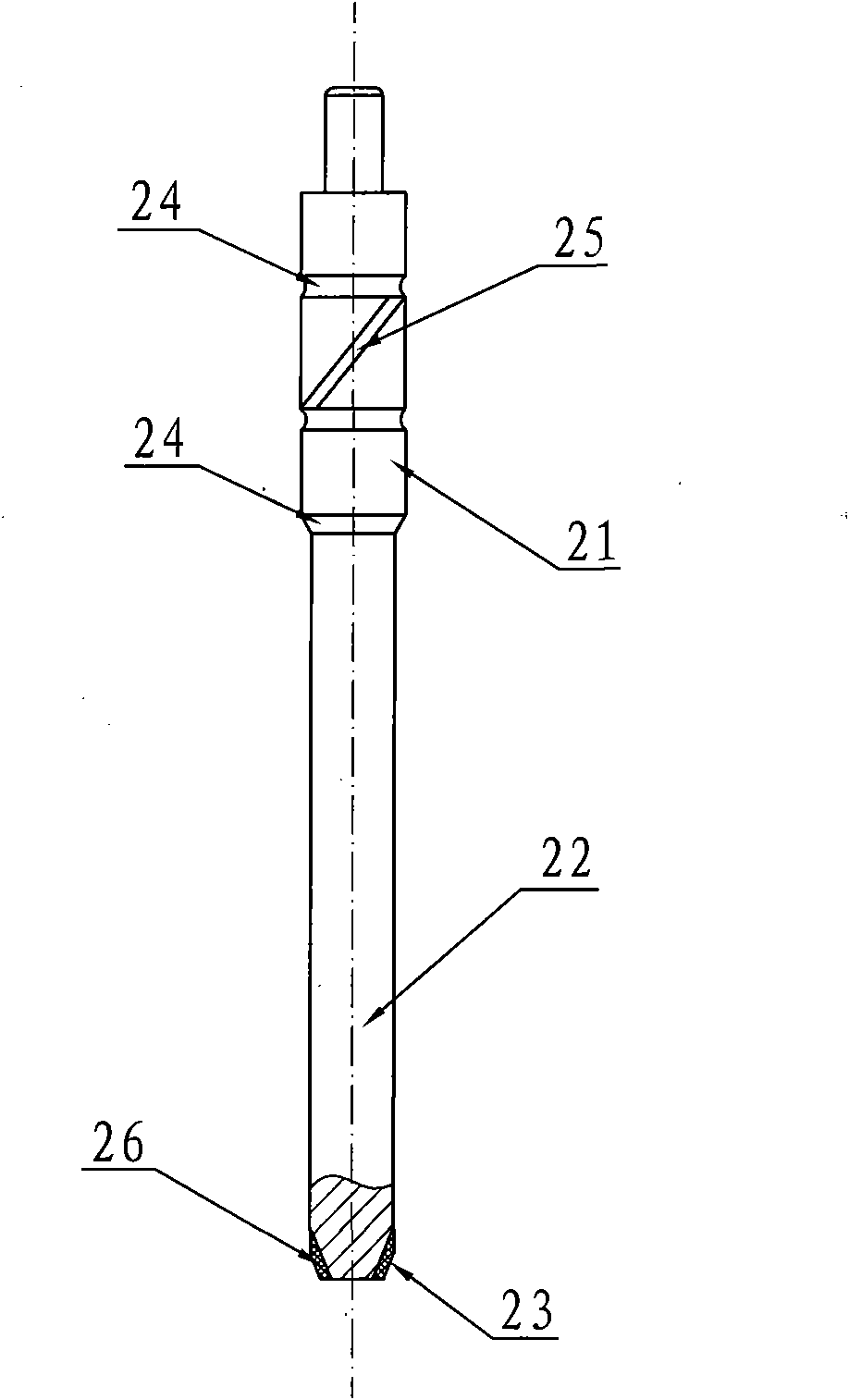
[0018] Embodiment 1: The diesel engine fuel injector assembly suitable for various fuels is composed of a needle valve body 1 and a needle valve 2, and a fuel channel 11, a fuel chamber 12, and a needle valve guide are arranged on the needle valve body 1. Hole 13, needle bar hole 14, sealing inner cone surface 15, oil injection hole 16 and lubricating oil channel 17, oil injection hole 16 is opened on the sealing inner cone surface 15, fuel channel 11 communicates with fuel chamber 12, lubricating oil The channel 17 is in communication with the guide hole 13 of the needle valve; the needle valve 2 is composed of a guide section 21, a tapered sealing rod 22 and a sealing outer cone surface 23, and the guide section 21 of the needle valve 2 is set on the needle on the needle valve body 1. In the valve guide hole 13, the conical surface sealing rod 22 is located in the needle rod hole 14, the sealing outer conical surface 23 of the needle valve 2 cooperates with the sealing inner ...

Embodiment 2

[0019] Embodiment 2: In Embodiment 1, the installation position of the lubricating oil groove 24 is related to the outlet position of the lubricating oil passage 17, so that the outlet of the lubricating oil passage 17 can communicate with the lubricating oil groove 24 when the needle valve 2 is at the lower limit position, or When the needle valve 2 is in the upper limit position, it communicates with the lubricating oil groove 24.

Embodiment 3

[0020] Embodiment 3: There are two lubricating oil grooves 24 on the needle valve 2, and the two lubricating oil grooves 24 divide the guide section 21 of the needle valve 2 into three equal parts in the axial direction, and the spiral oil grooves between the two lubricating oil grooves 24 25 connected.


PUM


Abstract

The invention discloses a diesel injector coupler applied to multiple fuels. A needle valve body is provided with a fuel passage, a fuel accommodating cavity, a needle valve guide hole, a needle bar hole, a sealed inner conical surface, an oil jet hole and a lubricating oil passage, wherein the oil jet hole is formed on the sealed inner conical surface; the fuel passage is communicated with the fuel accommodating cavity; the lubricating oil passage is communicated with the needle valve guide hole; a guide section is sleeved in the needle valve guide hole on the needle valve body; a conical surface sealing bar is positioned in the needle bar hole; the sealed outer conical surface of a needle valve is matched with the sealed inner conical surface of the needle valve body; the guide section of the needle valve is provided with a lubrication groove; and when the needle valve is positioned at a limit position, the lubrication groove is communicated with the lubricating oil passage. The lubrication groove is formed on the guide section of the needle valve so as to increase the axial length of the lubrication groove between the needle valve and the needle valve body, reduce the processing cost and prevent the needle valve and the needle valve body from being blocked due to lubrication lack; and an abrasion-resistant coating is arranged on the sealed outer conical surface of the needle valve so as to prolong the sealing life between the needle valve and the needle valve body and prevent the fuel liquid from leaking.

Description

Technical field: [0001] The invention relates to a fuel injector for a diesel engine, in particular to a fuel injector assembly of the fuel injector for a diesel engine. Background technique: [0002] The fuel injection pump is the most critical component in the combustion system of a diesel engine. It directly affects the emission index of the diesel engine. With the improvement of environmental requirements, the emission index of the diesel engine continues to increase. Now diesel engines are required to meet the emission requirements of Euro II and Euro III. At the same time, with the continuous expansion of the application range of diesel engine power, the social ownership of diesel engines is increasing, and the consumption of diesel is increasing year by year. Due to the limited and depleted oil resources in the world, countries all over the world are looking for alternative fuels for diesel. At present, dimethyl ether extracted from coal is recognized as a clean fuel ...

Claims


Application Information

Patent Timeline
IPC IPC(8): F02M61/10F01M9/10
Inventor 黄达保高留金
Owner CHANGZHOU YITONG FUEL EJECTOR MFG
Why Eureka
Try Eureka