
Additional reductant-free smoke denitration device and method for combustion equipment

A technology of combustion equipment and reducing agent, which is applied in the direction of separation methods, chemical instruments and methods, lighting and heating equipment, etc., can solve the problems of air preheater and other equipment such as corrosion, unsafety, and high denitrification cost, so as to reduce operating costs and improve Safety, benefit and remarkable effect

Active Publication Date: 2011-04-06
ZHEJIANG UNIV
View PDF3 Cites 14 Cited by
  • Summary
  • Abstract
  • Description
  • Claims
  • Application Information

AI Technical Summary

Problems solved by technology

[0005] At present, the SCR flue gas denitrification process of thermal power plants has the following disadvantages: first, a reducing agent needs to be added continuously during the denitrification process, and the cost of denitrification is high; second, the widely used reducing agent-pure ammonia and sulfur oxides in the flue gas generate ammonium Salt will cause corrosion and blockage of air preheater and other equipment, affecting the economy and reliability of system operation; third, pure ammonia has high safety requirements, and there are certain unsafe factors

Method used


Image

  • Additional reductant-free smoke denitration device and method for combustion equipment
  • Additional reductant-free smoke denitration device and method for combustion equipment
  • Additional reductant-free smoke denitration device and method for combustion equipment

Examples


Embodiment Construction

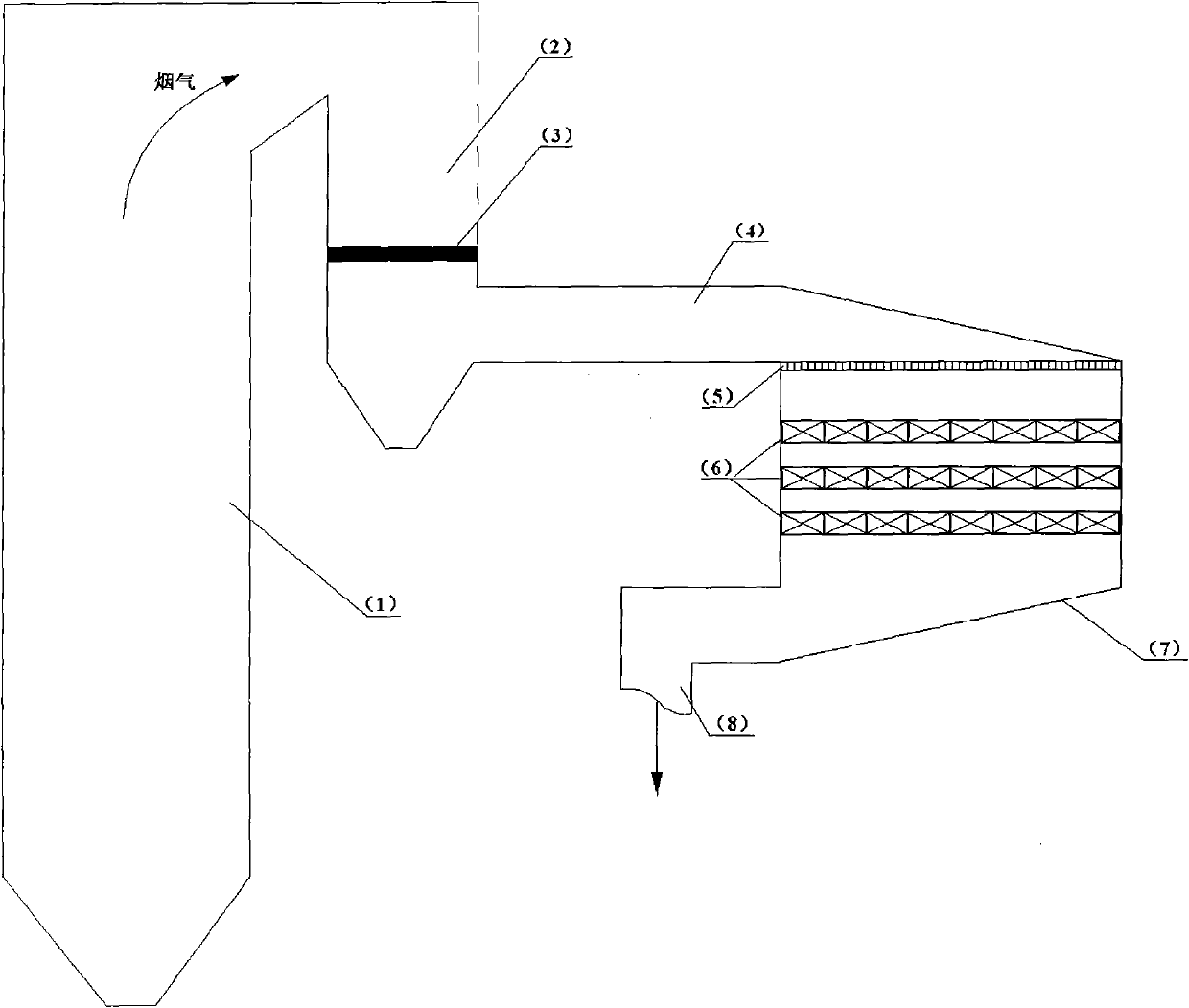
[0020] Such as figure 1 As shown, a flue gas denitrification device for combustion equipment without additional reducing agent is: the combustion equipment includes a connected boiler 1 and an economizer 2, and a discharge device 3 is arranged in the economizer 2, and the economizer 2. The inlet of the denitration reactor is connected to the flue 4, the rectification device 5, the catalyst bed 6, the denitration reactor 7, and the outlet of the denitration reactor to the flue 8, which are connected in sequence, and the denitration reactor 7 is provided with a catalyst bed 6.

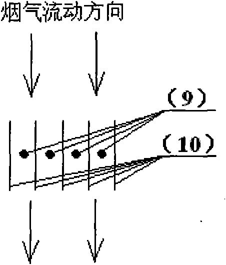
[0021] Such as image 3 As shown, the flue gas denitrification device for combustion equipment without additional reducing agent, the combustion equipment includes a connected boiler 1 and an economizer 2, which is characterized in that: the economizer 2, the inlet of the denitration reactor is connected to the flue 4, Rectification device 5, catalyst bed 6, denitrification reactor 7, denitrification re...


PUM


Abstract

The invention discloses an additional reductant-free smoke denitration device and method for combustion equipment. Smoke generated by a boiler flows through a coal economizer; a discharging device is distributed in an inlet connecting flue of the coal economizer or a denitration reactor; the discharging device adopts pulse discharge or direct current discharge; discharge voltage is controlled between critical coronal voltage and breakdown voltage; a high-energy electron e generated by discharging attacks a carbon dioxide molecule so that the carbon dioxide molecule is activated from a normal state to an activating state; the carbon dioxide molecule in the activating state is dissociated into CO and an active substance; part of CO2 is converted for producing CO by reacting; the smoke enters a denitration reactor through the inlet connecting flue of the denitration reactor and a rectifying device; NO and CO in the smoke react under the action of a catalyst bed layer in the denitration reactor and generate nontoxic N2 and CO2; and the reacting smoke is exhausted through an outlet connecting flue of the denitration reactor. The invention can be used for smoke denitration of a coal burning boiler, a gas burning boiler, an oil burning boiler, a biomass boiler, and the like and has the advantages of convenience for operation and obvious benefit.

Description

technical field [0001] The invention relates to combustion equipment, in particular to a flue gas denitrification device and method for combustion equipment without adding a reducing agent. Background technique [0002] my country's economy has maintained a momentum of rapid development for many years, which has triggered a huge demand for energy. From 1978 to 2009, my country's primary energy consumption increased from 570 million tons (calculated as standard coal) to 3.02 billion tons. my country's primary energy is dominated by coal, which accounts for more than 70% of the country's primary energy production and consumption for a long time, and about 75% of coal consumption is used for combustion. Fossil fuels (such as coal, oil, natural gas, etc.) and air will produce NOx when they burn at high temperature, and the NOx produced during the combustion process is mainly NO, which is about 95% (volume percentage). NOx has become one of the main causes of a series of serious...

Claims


Application Information

Patent Timeline
IPC IPC(8): B01D53/86B01D53/56F23J15/02
Inventor 高翔骆仲泱岑可法倪明江李明波徐甸施正伦周劲松方梦祥余春江王树荣程乐鸣王勤辉
Owner ZHEJIANG UNIV
Learn More