Method and device for constructing multiple CO2 laser system

A technology of laser system and construction method, applied in lasers, laser parts, phonon exciters, etc., can solve the problems of difficulty in improving the output, deformation of the output mirror, and the increase of the output power of the device that affects the performance of the device.

Inactive Publication Date: 2011-04-06
SICHUAN UNIV
View PDF4 Cites 5 Cited by
  • Summary
  • Abstract
  • Description
  • Claims
  • Application Information

AI Technical Summary

Problems solved by technology

The above three types of CO 2 Lasers have their own shortcomings, axial flow CO 2 Laser and cross-flow CO 2 The biggest disadvantage of the laser is that its device is particularly bulky, so the machine head and the laser can only be separated, and the laser output reaches the machine head after a long distance. Since there is no transmission CO 2 The optical fiber of the laser, so the linear transmission and direction change of the light wave and the control of the optical path after reaching the head of the processing machine are all realized by optical components and corresponding control measures
Slab waveguide CO 2 Although the laser can be directly installed in the processing machine, the laser is limit...

Method used


Image

  • Method and device for constructing multiple CO2 laser system
  • Method and device for constructing multiple CO2 laser system

Examples


Embodiment Construction

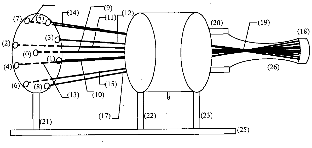
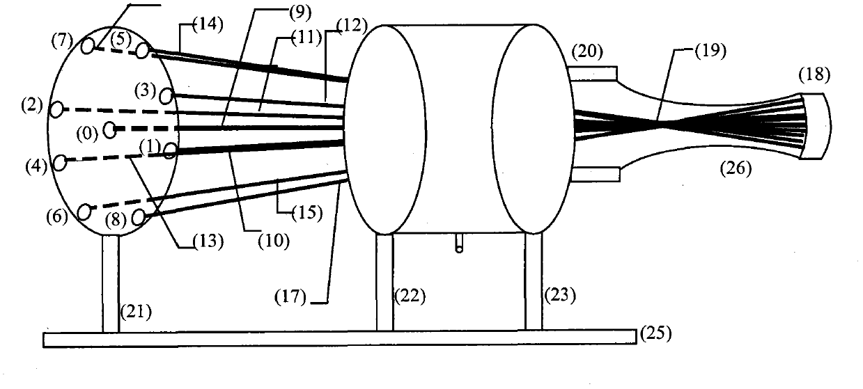
[0006] The discharge tubes on the axis and the discharge tubes placed symmetrically on the same conical surface are all inserted into the one-to-one corresponding circular holes of the fixed disc supports 21, 22 and 23, and protrude about 1 cm at 23 toward the output mirror. The gap between the outer edge of each discharge tube and the corresponding round holes of 21 and 22 is about 0.2 mm, and the tube and the disc are fixed elastically. 23 is a disc support made of stainless steel substrate, each corresponding hole is connected with a Kovar tube, each Kovar tube is connected with a glass transition joint, and the discharge tube passes through the inside of the Kovar tube and is connected with the right end of the transition joint. The cathodes of each discharge tube are located at a section of the total reflection mirror and are connected to the high-voltage end of the negative high-voltage power supply; and the anodes have no special requirements for electrode materials, so ...


PUM


Abstract

The invention relates to laser processing of optical engineering and modern manufacturing industry field, in particular to a method and a device thereof for constructing a compact high-power laser system with an intra-cavity common point consisting of a plurality of CO2 laser devices. The laser device consists of total reflection mirrors 0-8, discharge tubes 9-17, an output mirror 18, a hollow circular bracket 20, disc brackets 21, 22 and 23, a common water cooled jacket 24, a laser device bracket 25 and a hyperbolic glass tube 26. The axes of resonant cavities are intersected in one point of an intra-cavity public area, the resonant cavities share one output mirror, and the resonant cavities can acquire high-power output and protect the output mirror from being damaged by light and are favorable for long-term effective operation; and when the discharge areas at the public point continuously discharge and each discharge tube discharges in a pulse mode, beams produce phase-locked operation to a certain degree because stimulated particles at the public point of the public area synchronously stimulate intrinsic modes of the cavities to oscillate so as to facilitate converged laser processing and application.

Description

Technical field: [0001] The invention relates to laser processing in the field of optical engineering and modern manufacturing, mainly composed of multiple CO 2 The lasers constitute a compact high-power laser system with co-pointing in the cavity. Background technique: [0002] Laser processing is the use of the excellent directivity and high output power of the laser beam to perform high-precision and rapid processing of metal and non-metal materials. The lasers used for processing were mainly pulsed ruby ​​lasers and neodymium glass lasers before 1967. Afterwards, with the continuous oscillation of CO 2 As the output power of lasers and Nd:YAG lasers increases, more processing is performed using these two lasers. According to the data in recent years, the annual output value of laser processing systems in the world is about more than 3 billion US dollars, mainly CO 2 lasers and Nd:YAG lasers. CO 2 The annual output value of the laser processing system is about 1.5 b...

Claims


Application Information

Patent Timeline
IPC IPC(8): H01S3/082
Inventor 陈梅赵晓凤刘静伦
Owner SICHUAN UNIV
Why Eureka
Try Eureka