
Method for controlling laser power supply energy based on DSP (Digital Signal Processor)

A laser power supply and energy control technology, applied in excitation methods/devices, lasers, laser components, etc., can solve the problems of easily damaged laser power supply, power supply burnout, unstable laser energy output, etc., to avoid burning the power supply, avoid straight-through effect

Inactive Publication Date: 2011-04-06
NO 709 RES INST OF CHINA SHIPBUILDING IND CORP
View PDF1 Cites 10 Cited by
  • Summary
  • Abstract
  • Description
  • Claims
  • Application Information

AI Technical Summary

Problems solved by technology

[0002] CO 2 Laser power supplies are widely used in the energy supply of gas laser tubes in various fields such as welding, cutting, marking, scribing, and film engraving; Development of Laser Industry
Usually, CO 2 When the laser power supply is no-load or poorly insulated, a high-voltage electric field is formed between the high-voltage connector and the power supply casing, and it is easy to cause the power supply to burn out through ionization arc discharge
If the laser tube is damaged or leaks seriously enough to change its own load characteristics, it will also endanger the excitation power supply.

Method used


Image

  • Method for controlling laser power supply energy based on DSP (Digital Signal Processor)
  • Method for controlling laser power supply energy based on DSP (Digital Signal Processor)
  • Method for controlling laser power supply energy based on DSP (Digital Signal Processor)

Examples


Embodiment Construction

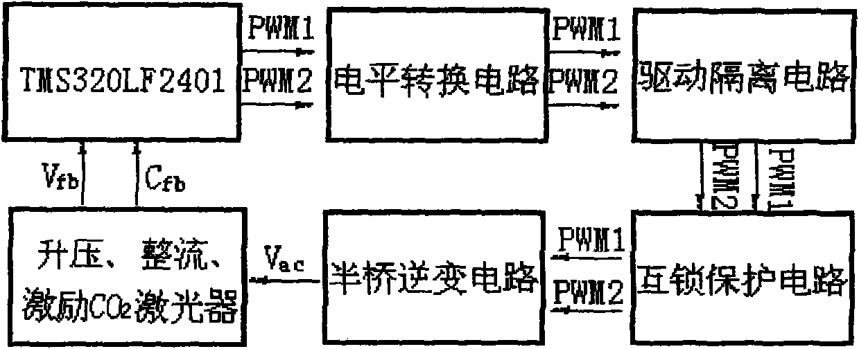
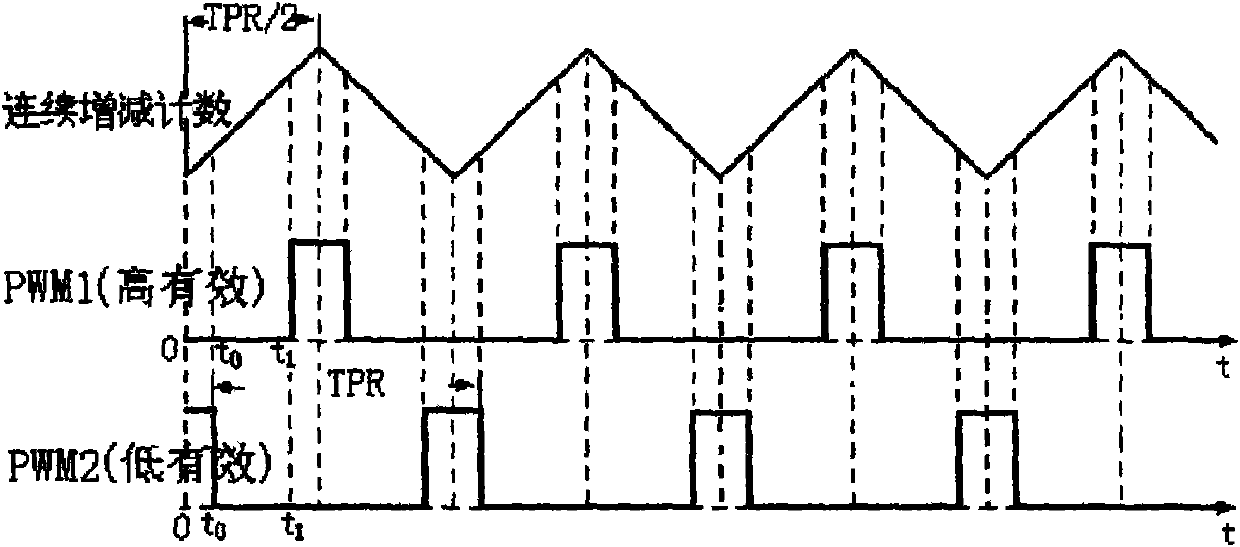
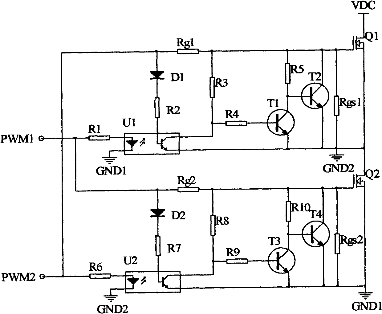
[0018] according to Figure 1-4 As shown, a DSP-based laser power supply energy control method: the on-chip integrated AD of the digital signal processor TMS320LF2401 is used to collect the feedback voltage generated by the high-voltage package and the voltage corresponding to the output current of the CO2 laser tube, according to the principle of constant voltage and constant current feedback control Calculate and update the duty cycle of the PWM wave in real time, and then generate high frequency and high voltage through the half bridge conversion circuit, use the high voltage package to boost the voltage, rectify and excite the CO2 laser tube to output laser. The PWM wave signal generated by the TMS320LF2401 digital signal processor is at TTL level, and then drives the half-bridge conversion circuit through a level conversion circuit, a signal isolation circuit and a signal interlock protection circuit. The method of online identification of abnormal conditions such as no-l...


PUM


Abstract

The invention discloses a CO2 laser power supply intelligent controller developed based on a digital signal processor (DSP) TMS320LF2410. The quickness and the stability of laser energy can be realized by adopting a method of glow start constant-voltage control and work constant-current control. The invention provides an on-line discrimination method for laser power supply idle load, laser tube damage and other abnormal conditions and a drive signal isolating interlocking circuit aiming at the potential hazard for intervening and causing the straightway of a bridge type circuit. The inventionhas the advantages that: the laser output energy can be quickly and accurately stabilized by adopting the DSP to carry out constant-voltage and constant-current control on the laser power supply; thestraightway of an upper bridge arm and a lower bridge arm at abnormal state can be effectively avoided by directly using control signals of MOSFET (Metal-Oxide -Semiconductor Field Effect Transistor)tube grid electrodes of the upper bridge arm and the lower bridge arm as an interlocking signal source; and the laser source idle load, the damage of the laser tube and other abnormal conditions can be identified on line and the work of the power supply can be instantly stopped when the CO2 laser source is in open circuit and the damage of the laser tube and other abnormal conditions generate, thereby the phenomenon that the power supply is burnt down because the high voltage cannot be discharged in time can be effectively avoided.

Description

technical field [0001] The present invention relates to CO 2 Development of digital intelligent controller for laser power supply. The controller uses a digital signal processor to generate the driving signal of the bridge circuit, and designs the circuit to directly implement interlock protection on the driving signal of the MOSFET tube of the upper and lower bridge arms, so as to avoid the hidden trouble caused by interference, and proposes a laser energy stabilization process A method for real-time identification of abnormal conditions such as laser power supply no-load and laser tube damage. Background technique [0002] CO 2 Laser power supplies are widely used in the energy supply of gas laser tubes in various fields such as welding, cutting, marking, scribing, and film engraving; Development of the laser industry. Usually, CO 2 When the laser power supply is no-load or poorly insulated, a high-voltage electric field is formed between the high-voltage connector an...

Claims


Application Information

Patent Timeline
Patent Type & Authority Applications(China)
IPC IPC(8): H01S3/09H01S3/104
Inventor 肖刚占江山王军彭琪
Owner NO 709 RES INST OF CHINA SHIPBUILDING IND CORP
Learn More