Circularly polarized ceramic antenna based on coupling and feeding of strip line via multiple slots

A technology of coupled feed and ceramic antenna, applied in the direction of antenna, antenna grounding device, antenna support/installation device, etc., can solve the problems of inability to guarantee the coverage of mobile satellite communication, increase of aerodynamic resistance, insufficient beam width, etc. , to achieve the effect of good circularly polarized antenna performance, improved grounding performance, and compact structure

Inactive Publication Date: 2011-04-13
SOUTH CHINA UNIV OF TECH
View PDF2 Cites 37 Cited by
  • Summary
  • Abstract
  • Description
  • Claims
  • Application Information

AI Technical Summary

Problems solved by technology

[0007] Traditional helical antennas are often used in satellite navigation systems to generate circularly polarized wave propagation, since the antenna needs to extend upwards from the surface of the grounded metal plate to a height of λ 0 / 4~λ 0 / 2 (where λ 0 for the antenna operating wavelength) a helix, so it's not well styled and adds aerodynamic drag
The low-profile microstrip antenna can make up for the above shortcomings, but the traditional single-feed microstrip circularly polarized antenna still has the following disadvantages: (1) There is not enough beam width to ensure a wide enough coverage for mobile satellite communications; (2) When there is enough beam width, the impedance bandwidth is not enough
Although the radiation beam width of the microstrip antenna is reduced by using a dielectric material with a high dielectric constant or using microstrip slotting technology to produce a wide radiation beam, this method reduces the impedance bandwidth and cannot meet the requirements.

Method used


Image

  • Circularly polarized ceramic antenna based on coupling and feeding of strip line via multiple slots
  • Circularly polarized ceramic antenna based on coupling and feeding of strip line via multiple slots
  • Circularly polarized ceramic antenna based on coupling and feeding of strip line via multiple slots

Examples


Embodiment Construction

[0043] The present invention will be described in detail below in conjunction with the accompanying drawings, but the embodiments of the present invention are not limited thereto.

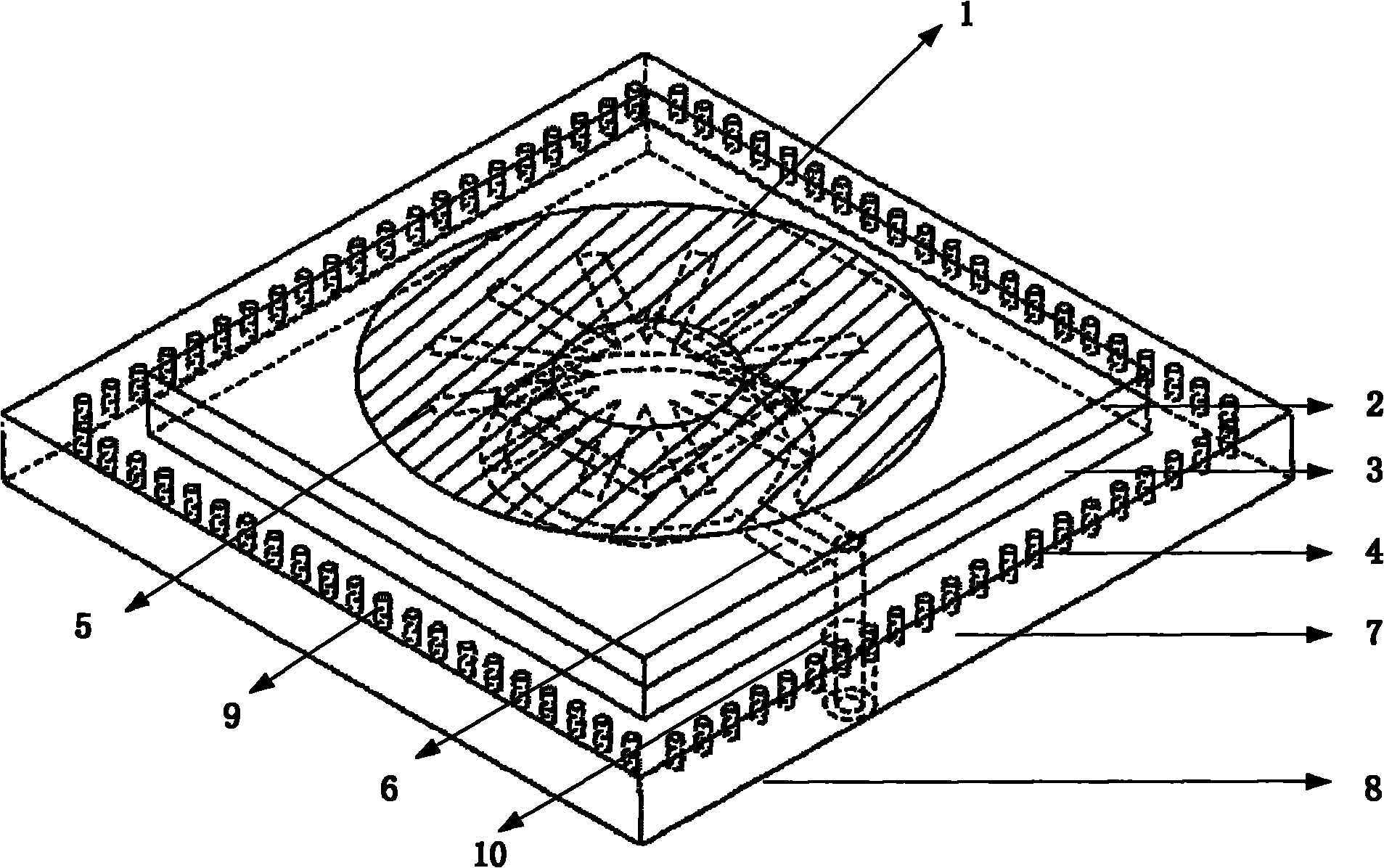
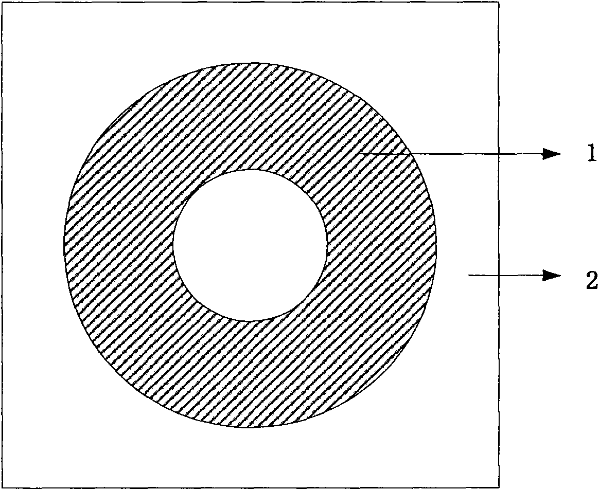
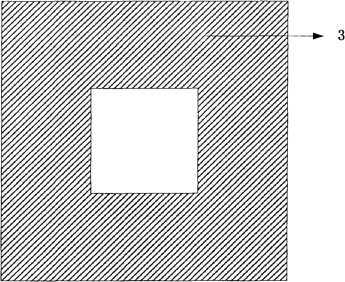
[0044] Such as figure 1 , 2a , 2b, 2c, 2d, and 2e, a circularly polarized ceramic antenna based on stripline multi-slot coupling feeding is implemented in the form of a microstrip circuit, including an upper layer microstrip antenna radiator 1, an upper layer dielectric substrate 2. The middle dielectric substrate 3 , the lower feed strip line and the coaxial feed line 10 . The lower feeder stripline consists of a dielectric substrate layer 7, an upper metal floor layer 4 attached to the upper surface of the dielectric substrate, a lower metal floor layer 8 attached to the lower surface of the dielectric substrate, and a metal feeder 6 arranged in the middle of the dielectric substrate layer . Wherein, the center of the upper metal base layer 4 is provided with a feed slot 5 composed of 3 cross ...


PUM


Abstract

The invention discloses a circularly polarized ceramic antenna based on coupling and feeding of a strip line via multiple slots, comprising an upper microstrip antenna radiator, an upper dielectric substrate, a medium dielectric substrate, a lower feed strip line and a coaxial feeder, wherein the lower feed strip line comprises a dielectric substrate layer, upper and lower metal floor layers attached to the upper and lower surfaces of the dielectric substrate and a metal feeder in the middle of the dielectric substrate layer; feed slots formed by three cross slots are arranged in the center of the upper metal floor of the strip line; the metal feeder couples and feeds the upper microstrip antenna structure via the slots; and the upper and lower metal floor layers of the strip line are connected by cylindrical via holes. The antenna adopts the feed slots formed by three cross slots to increase operation bandwidth and the 3dB circularly polarized axial ratio bandwidth, adopts the squarering dielectric substrate and the strip line for coupling and feeding to increase the gain, has the characteristics of miniaturization, band broadening and compact structure, and is convenient in processing and integration.

Description

technical field [0001] The invention relates to a satellite navigation and positioning antenna, in particular to a circularly polarized ceramic antenna based on stripline multi-slot coupling feeding. Multiple navigation systems in the B 1 frequency band (1561.098MHz) of the system and the L1 frequency band (1575.42MHz) of the US GPS system. Background technique [0002] The satellite navigation industry is a national strategic high-tech industry. It is a typical technology-intensive and service-oriented IT industry. Its development prospects are very broad. It has become one of the eight major wireless industries in the world. The rapid information industry has become another new growth point of the third IT economy. The satellite navigation and positioning industry represented by the US Global Positioning System (GPS) has gradually become a global high-tech industry. my country's satellite navigation industry is entering a critical moment of rapid industrialization develo...

Claims


Application Information

Patent Timeline
Patent Type & Authority Applications(China)
IPC IPC(8): H01Q1/14H01Q1/48H01Q13/08
Inventor 胡斌杰王晓欣章秀银
Owner SOUTH CHINA UNIV OF TECH
Why Eureka
Try Eureka