Method for manufacturing carbon nanotube solid phase micro-extraction head

A technology of solid-phase microextraction head and carbon nanotubes, which is applied in chemical instruments and methods, and other chemical processes, can solve the problems of difficult surface modification, poor mechanical properties, coating peeling, etc. Crushed, excellent adsorption performance, and prolonging the service life

Active Publication Date: 2011-04-20
LANZHOU INST OF CHEM PHYSICS CHINESE ACAD OF SCI
View PDF2 Cites 7 Cited by
  • Summary
  • Abstract
  • Description
  • Claims
  • Application Information

AI Technical Summary

Problems solved by technology

At present, the commonly used methods for preparing carbon nanotube solid-phase microextraction head include: direct adhesion coating method and physical coating method, but these preparation methods all have obvious deficiencies: the use of binder in the direct adhesion coating method makes the extraction head Unstable in solvent, high temperature and strong acid-base solution, easy to swell and cause the coating to fall off, greatly reducing the service life and application range of the extraction head (CN200810026734); in the physical coating method, the carbon nanotubes and the carrier themselves only rely on physical The effect is combined, the bonding between the coating and the carrier is poor, and the service life of the extraction head is short (CN200810071369)
Quartz is a common material used to prepare solid-phase microextraction head carriers. This material has poor mechanical properties, and the quartz carrier is prone to breakage during operation, which seriously affects the service life of the extraction head.
In order to solve this problem, many scholars began to devote themselves to the research of wire carriers, and prepared some solid-phase microextraction heads with titanium wires, nickel wires, stainless steel wires, etc. as carriers. However, although these wires have certain mechanical strength, However, its surface is not easy to modify, which limits the use of metal wire as a carrier to prepare solid-phase microextraction heads.

Method used


Image

  • Method for manufacturing carbon nanotube solid phase micro-extraction head
  • Method for manufacturing carbon nanotube solid phase micro-extraction head

Examples


Embodiment 1

[0030] 1. Deposit silicon film on the surface of stainless steel wire by magnetron sputtering. The metal wire was ultrasonically cleaned with absolute alcohol, distilled water, and acetone for 10 min, and then dried with nitrogen and placed in the deposition chamber. Pump the air pressure in the vacuum chamber to 6×10 -3 Below Pa, feed high-purity argon until the pressure is 3.0Pa. Turn on the pulse bias power supply, adjust the voltage value to -200V, and set the duty cycle to 80%, and perform argon plasma bombardment cleaning for 10 minutes to remove the oxide layer on the metal surface. Then deposit a silicon transition layer: adjust the argon flow to maintain the chamber pressure at 2.5×10 -1 Pa, turn on the intermediate frequency sputtering power supply and the pulse bias power supply, adjust the sputtering current to 20A, the pulse bias voltage to -1000V, and the pulse duty cycle to 20%, and turn it off after the thickness of the transition layer reaches 500nm.

[003...

Embodiment 2

[0035] 1. Deposit silicon film on the surface of stainless steel wire by magnetron sputtering. The stainless steel wire was ultrasonically cleaned with absolute alcohol, distilled water, and acetone for 10 min, and then dried with nitrogen gas and placed in the deposition chamber. Pump the air pressure in the vacuum chamber to 6×10 -3 Below Pa, feed high-purity argon until the pressure is 3.0Pa. Turn on the pulse bias power supply, adjust the voltage value to -200V, and set the duty cycle to 80%, and perform argon plasma bombardment cleaning for 10 minutes to remove the oxide layer on the metal surface. Then deposit a silicon transition layer: adjust the flow of argon to maintain the chamber pressure at 5.5×10 -1 Pa, turn on the intermediate frequency sputtering power supply and the pulse bias power supply, adjust the sputtering current to 8A, the pulse bias voltage to -400V, and the pulse duty cycle to 80%, and turn it off after the thickness of the transition layer reaches...

Embodiment 3

[0040] 1. Deposit a silicon film on the surface of the metal wire by magnetron sputtering. The metal wire was ultrasonically cleaned with absolute alcohol, distilled water, and acetone for 10 min, and then dried with nitrogen and placed in the deposition chamber. Pump the air pressure in the vacuum chamber to 6×10 -3 Below Pa, feed high-purity argon until the pressure is 3.0Pa. Turn on the pulse bias power supply, adjust the voltage value to -200V, and set the duty cycle to 80%, and perform argon plasma bombardment cleaning for 10 minutes to remove the oxide layer on the metal surface. Then deposit a silicon transition layer: adjust the flow of argon to maintain the chamber pressure at 5.5×10 -1 Pa, turn on the intermediate frequency sputtering power supply and the pulse bias power supply, adjust the sputtering current to 4A, the pulse bias voltage to -100V, and the pulse duty cycle to 40%, and turn it off after the thickness of the transition layer reaches 600nm.

[0041] ...


PUM


Abstract

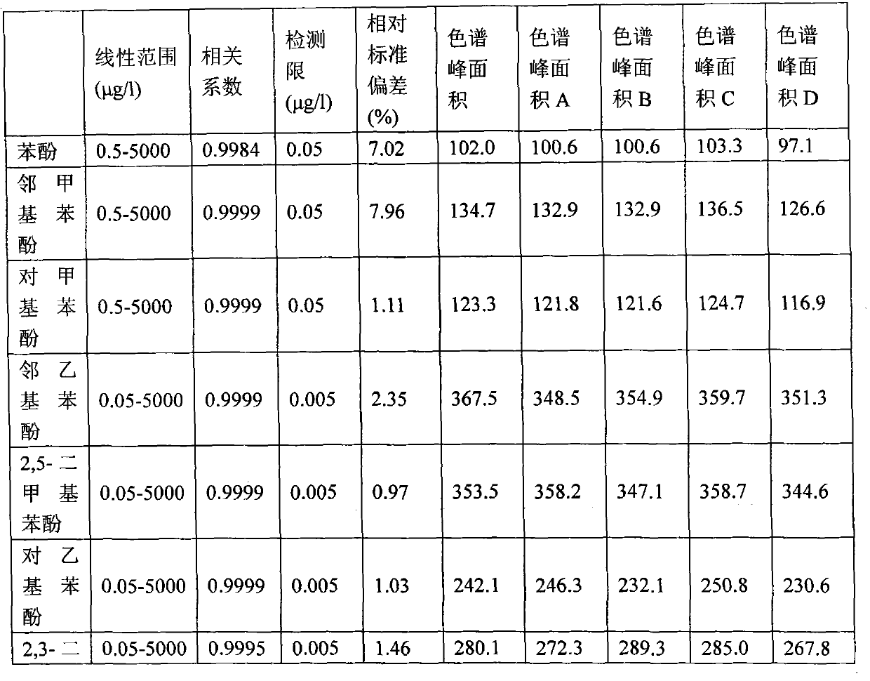
The invention discloses a method for manufacturing a carbon nanotube solid phase micro-extraction head. The invention selects stainless steel filaments as a carrier, and employs the method of magnetron sputtering to deposit a silicon thin film on the surface. By surface activation modification, carbon nanotubes and the carrier silicon thin film possess special active groups. Chemical bond connection between the carbon nanotubes and the stainless steel filament carrier is achieved through the chemical reaction between the active groups. Finally, according to the properties of carbon nanotube materials, multilayer carbon nanotube self-assembly is carried out on the surface of a bonded extraction head, and the solid phase micro-extraction head is obtained. The solid phase micro-extraction head is characterized by high mechanical strength, excellent absorption capability, good reproducibility, long service lifetime and so on and can be applied in enrichment analysis of trace quantity ingredients in real samples in fields of food, environment, medicament, biochemistry and so on.

Description

technical field [0001] The invention relates to a method for preparing a carbon nanotube solid-phase micro-extraction head on a stainless steel wire carrier. Background technique [0002] Solid phase microextraction (solid phase microextraction, SPME) is an efficient and rapid new separation technology developed in the 1990s. Due to its advantages, it has been favored by analysts and is widely used in the enrichment analysis of trace components in actual samples such as food, environment, medicine and biochemistry. The core of solid phase microextraction technology is the preparation of solid phase microextraction head. How to prepare solid-phase microextraction tips with excellent adsorption performance and durability is the bottleneck of the development of solid-phase microextraction technology. Carbon nanotube (CNT) material is recognized as a very good adsorbent, it has the advantages of strong adsorption capacity, large specific surface area, stable properties and spe...

Claims


Application Information

Patent Timeline
Patent Type & Authority Applications(China)
IPC IPC(8): B01J20/20B01J20/32
Inventor 蒋生祥刘红妹李菊白刘霞
Owner LANZHOU INST OF CHEM PHYSICS CHINESE ACAD OF SCI
Why Eureka
Try Eureka