Multistage continuous photocatalysis water purification reactor and water treatment method thereof

A photocatalyst and reactor technology, applied in the field of environmental purification, can solve the problems of photocatalyst shedding and loss, photocatalyst complexity, and failure to reach a practical scale.

Inactive Publication Date: 2011-04-20
INST OF CHEM CHINESE ACAD OF SCI
View PDF4 Cites 5 Cited by
  • Summary
  • Abstract
  • Description
  • Claims
  • Application Information

AI Technical Summary

Problems solved by technology

But there are three main problems: (1) There are intractable contradictions between the particle size and photocatalytic activity of the photocatalyst, as well as the suspension and deposition. Deposition occurs and photocatalytic activity decreases
(2) The light scattering and transmission of the photocatalyst affect the effective absorption of light by the photocatalyst; (3) The photocatalyst is difficult to separate and recover
However, the supported photocatalytic reactor also has the following problems: (1) The preparation of the photocatalyst is relatively complicated; (2) The long-term use of the photocatalyst causes shedding and loss; (3) The light absorption efficiency of the photocatalyst is low
In addition, the current photocatalytic reactors mainly focus on TiO 2 The development of heterogeneous photocatalytic reactors did not consider the application of other photocatalytic systems with the same high efficiency, such as metal and their complex photocatalytic systems, and the photocatalytic reactors developed in the past were all for the purpose of demonstration effect, water treatment The capacity is extremely limited, and there is currently no photocatalytic water purification reactor capable of reaching a practical scale

Method used


Image

  • Multistage continuous photocatalysis water purification reactor and water treatment method thereof
  • Multistage continuous photocatalysis water purification reactor and water treatment method thereof

Examples


Embodiment 1

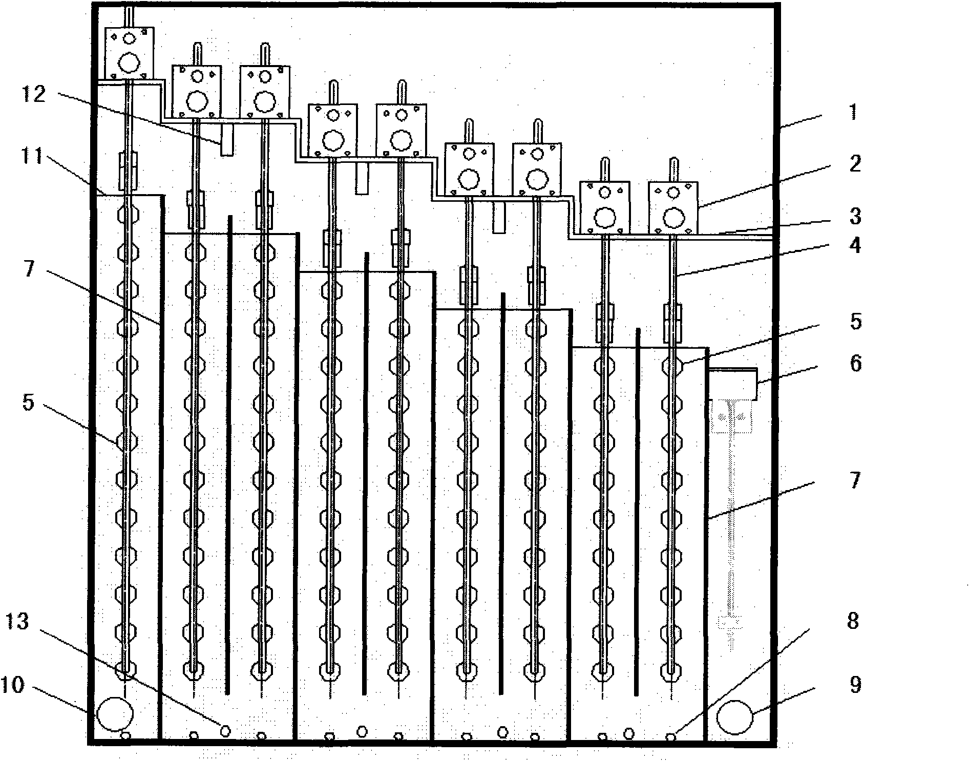
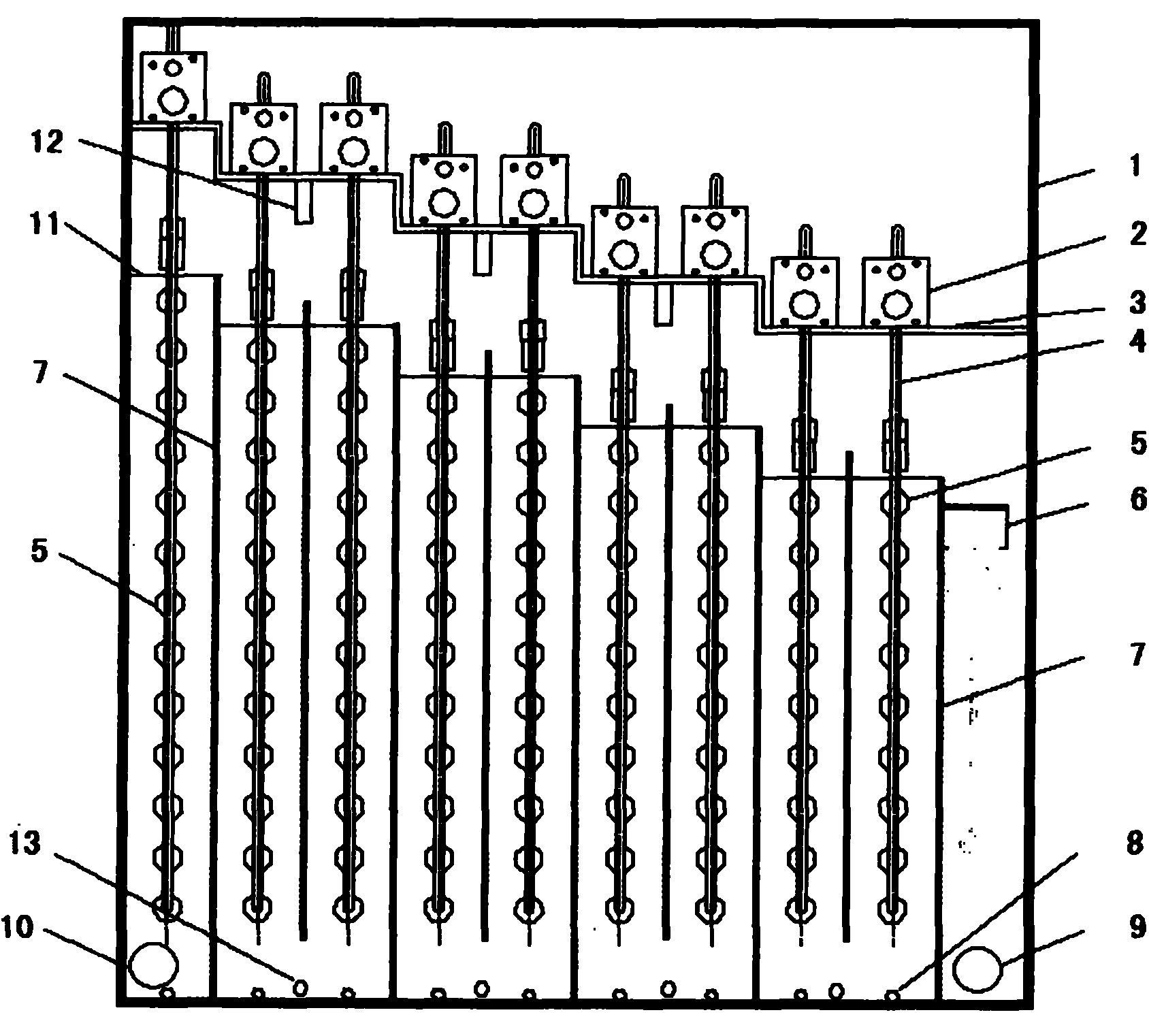
[0035] See figure 1 , the multi-stage continuous photocatalytic water purification reactor mainly includes three parts: contact pool, light source module, and switch control system;

[0036] Nine detachable partitions 7 made of polytetrafluoroethylene are fixedly installed in the nine slots of the inner pool wall of a rectangular contact pool made of stainless steel. The thickness of the detachable partition is Both are 3 cm, and the distance between the two adjacent detachable partitions 7 is 10 cm, and is defined as a single-stage processing system, with a total of 8-stage processing systems; the first detachable The space between the partition plate 7 and the pool wall of the contact pool is defined as the primary treatment system, and the space between the last removable partition plate 7 and the pool wall of the contact pool is defined as the final treatment system. system.

[0037] A water inlet 10 is provided at the bottom of the contact tank in the first-level treatm...

Embodiment 2

[0044] The basic structure of the multi-stage continuous photocatalytic water purification reactor is as in Example 1, which mainly includes three parts: the contact pool, the light source module, and the switch control system; only:

[0045] In the 5 draw-in slots of the inner pool wall of the contact pool, 5 detachable partitions 7 made of plexiglass are fixedly installed respectively. The thickness of the detachable partitions is 1 cm, and the adjacent two The distance between the removable partitions 7 is 28 centimeters, and is defined as a single-stage treatment system, a total of 4 treatment systems; the first piece of the removable partition 7 and the pool wall of the contact pool The space between them is defined as the primary treatment system, and the space between the last removable partition 7 and the pool wall of the contact pool is defined as the final treatment system.

[0046] The horizontal height of the 5 detachable partitions 7 that have been installed is th...

Embodiment 3

[0050] The basic structure of the multi-stage continuous photocatalytic water purification reactor is as in Example 1, which mainly includes three parts: the contact pool, the light source module, and the switch control system; only:

[0051] In the 8 slots of the inner pool wall of the contact pool, 8 removable partitions 7 made of stainless steel are fixedly installed respectively. The thickness of the removable partitions is 0.5 cm, and the adjacent two The distance between the detachable partitions 7 is 15 centimeters, and is defined as a single-stage treatment system, a total of 7 treatment systems; the first piece of detachable partitions 7 and the pool wall of the contact pool The space between them is defined as the primary treatment system, and the space between the last removable partition 7 and the pool wall of the contact pool is defined as the final treatment system.

[0052] The horizontal height of the installed detachable partition is that the level of the two ...


PUM

PropertyMeasurementUnit
thicknessaaaaaaaaaa
thicknessaaaaaaaaaa
thicknessaaaaaaaaaa

Abstract

The invention relates to a multistage continuous photocatalysis water purification reactor and a water treatment method thereof. The reactor comprises a contact tank, a light source module and a switch control system, wherein a plurality of clamping grooves in the inner wall of the contact tank are correspondingly and fixedly provided with a plurality of dismountable clapboards; the spaces among the dismountable clapboards form single-stage treatment systems; each single-stage treatment system is provided with the light source module comprising a light source bent frame and more than one tube installed on the light source bent frame; the bottom of the contact tank is provided with a water inlet, a water outlet, an on-line sampling port and a drain outlet respectively; the bottom of the contact tank below the light source bent frame is fixedly provided with an aerator pipe and an aeration stone for rising bubbles; and the switch control system independently controls the on and off of the tube in each light source module. The reactor can be used for deep purification treatment on high-toxicity and low-concentration poisonous and organic pollutants and common organic pollutants in the polluted drinking water, industrial waste water and urban domestic sewage.

Description

technical field [0001] The invention belongs to the technical field of environmental purification, in particular to a multi-stage continuous photocatalytic water purification reactor and a water treatment method thereof. Background technique [0002] Photocatalytic oxidation systems using visible light or ultraviolet light to excite photocatalysts to activate oxidants such as molecular oxygen or hydrogen peroxide have attracted extensive attention and applications in recent years, such as photolysis of water, selective organic synthesis, water treatment, air purification, and antitumor applications. etc., especially in the treatment of pollutants, the use of the generated active oxygen species can effectively oxidize and decompose most of the toxic organic pollutants into carbon dioxide, water and inorganic ions. The most promising photocatalytic technology can be divided into two categories according to the photocatalyst used: semiconductor oxides (such as TiO 2 and its mo...

Claims


Application Information

Patent Timeline
Patent Type & Authority Applications(China)
IPC IPC(8): C02F1/30C02F1/72
CPCY02W10/37
Inventor 赵进才籍宏伟马万红陈春城
Owner INST OF CHEM CHINESE ACAD OF SCI
Why Eureka
Try Eureka