

Digital phase-locked loop based on Cordic algorithm
A digital phase-locked loop and algorithm technology, applied in the automatic control of power, electrical components, etc., can solve the problems of signal instability, large phase error between digital sine signal and square wave signal, etc., and achieve the effect of short locking time
- Summary
- Abstract
- Description
- Claims
- Application Information
AI Technical Summary
Problems solved by technology
Method used
Image

Examples
Embodiment Construction
[0031] The present invention will be described in more detail below in conjunction with the accompanying drawings and specific embodiments.
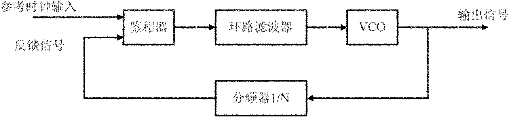
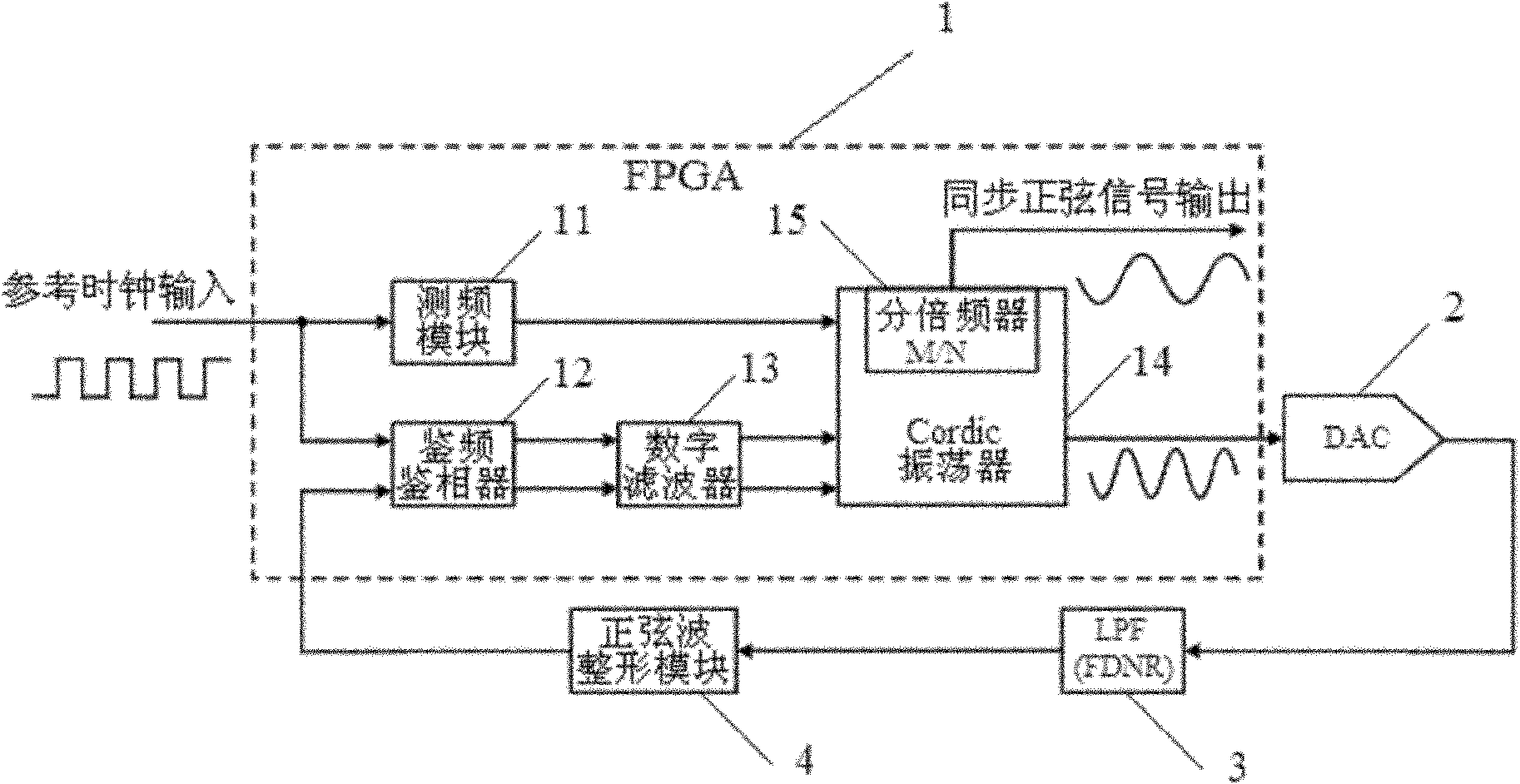
[0032] see figure 2 Shown is a schematic block diagram of a digital phase-locked loop provided by the present invention. The main module of this digital phase-locked loop is realized by programmable logic device (FPGA) 1, and frequency measurement module 11, frequency discrimination phase detector 12, digital filter 13, Cordic oscillator 14 are set in FPGA1, and this digitally controlled oscillator 14 internally sets the M times frequency divider 15.
[0033] The main function of the frequency measurement module 11 is to measure the frequency of the reference clock input signal. In this embodiment, the frequency measurement module 11 adopts the frequency division frequency measurement method to perform different frequency division measurements on signals in different frequency bands, and then input the measurement data to the Cordic o...
PUM
 Abstract
Description
Claims
Application Information