Natural ventilation air-cooling condenser

An air-cooled condenser and natural ventilation technology, which is applied in the field of heat exchange, can solve difficulties, reduce turbine output, increase air-cooled condenser device support facilities, and install investment to achieve the effect of saving support facilities

Inactive Publication Date: 2011-05-11
李宁
View PDF6 Cites 12 Cited by
  • Summary
  • Abstract
  • Description
  • Claims
  • Application Information

AI Technical Summary

Problems solved by technology

[0005] Disadvantage 1 is that the air-cooled condenser is arranged on the platform inside the tower, the steam main pipe and branch pipes are far away from the steam distribution pipe, and there are many elbows, which not only increases the pipeline investment, but also increases the resistance of the exhaust steam pipeline, thereby reducing the turbine output ;
[0006] Disadvantage 2 is that the air-cooled condenser is arranged in the natural ventilation tower with a flat, conical or stepped structure. Since the air-cooled condenser must leave room for cold air to enter, such as the thousands-ton air-cooled condenser of a 600Mw unit The height of the condenser must be placed on a platform of at least 20 meters in the tower, which will inevitably increase the support facilities and installation investment of the air-cooled condenser device;
[0007] Disadvantage 3, because the natural ventilation tower uses the prod

Method used


Image

  • Natural ventilation air-cooling condenser
  • Natural ventilation air-cooling condenser
  • Natural ventilation air-cooling condenser

Examples


Embodiment Construction

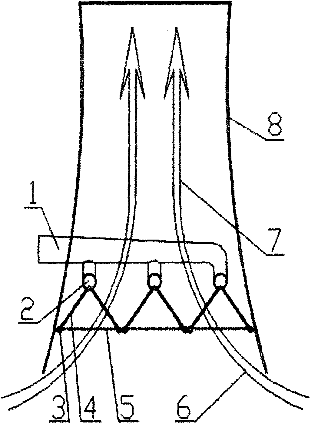
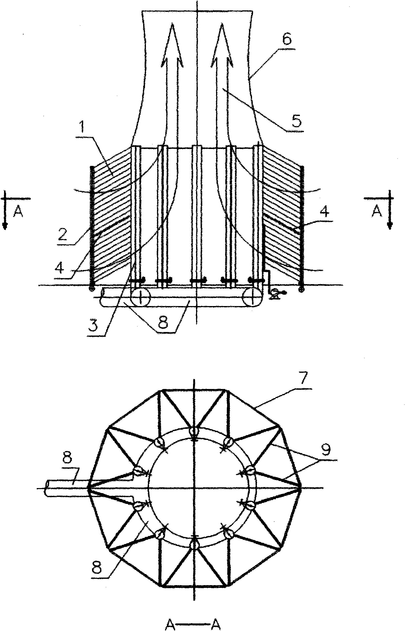
[0039] The specific implementation of the present invention will be described below by taking a 600Mw natural draft air-cooled condenser as an example.

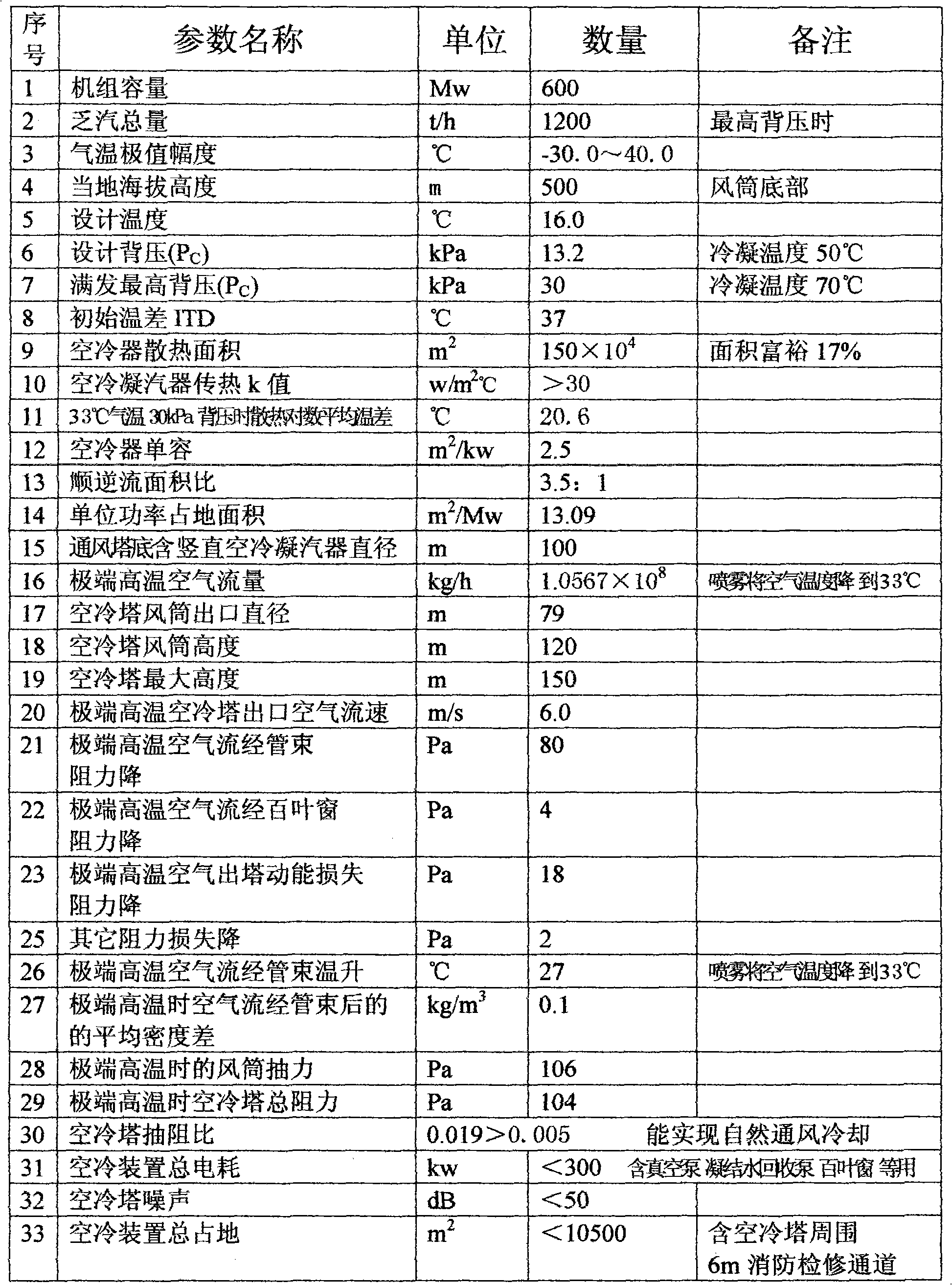
[0040] 1. According to the rated power output of the ultra-supercritical 600Mw unit at a temperature of 33°C in summer, the total amount of exhaust steam is 1200 tons per hour, and the condensing load of the air-cooled condenser is 2.853×10 9 kJ / h, the temperature of the air flowing through the air-cooled condenser rises from 33°C to 60°C, the temperature rise is 27°C, and the required air flow rate is 1.0567×10 8 kg / h, assuming that the flow velocity of the hot air out of the ventilation tower is the maximum 6m / s, and the density of the air at 60°C is 1.0kg / m 3 , the outlet diameter of the ventilation tower is: 79m. The rest of the basic design data are shown in the table below:

[0041]

[0042] The 600Mw large-scale naturally ventilated air-cooled condenser of the power station designed by the present invention can be...


PUM


Abstract

The invention provides a natural ventilation air-cooling condenser, which belongs to the field of heat exchange, and in particular relates to an air-cooling condenser in an electric power plant taking air as a cooling medium. The conventional air-cooling condenser is high in power consumption, high in investment cost and poor in anti-wind capability. In the design, the air-cooling condenser is designed into a heat exchanging unit component which has a vertical windward side structure and combined with a natural ventilation tower to form the natural ventilation air-cooling condenser of which a heat exchanging component is arranged at the periphery of the lower part of the ventilation tower. Waste steams become water after entering the heat exchanging component and being subjected to heat exchange with the air outside a pipe. The density of the air which absorbs heat is reduced to generate a lift force, so the air ascends to the tower top in the natural ventilation tower and enters the high altitude, and natural circulation of the cold air and the hot air before and after the air-cooling condenser is realized. By the air-cooling condenser having the structure, the investment and the power consumption on a high platform and a fan in the conventional direct air-cooling technology are saved, the problem that the hot air circulation and the heavy wind in the conventional direct air-cooling technology endangers the safety economic operation of the electric power plant is eliminated, and the energy consumption cost of the electric power plant is reduced.

Description

technical field [0001] The invention belongs to the field of heat exchange, in particular to a cooling device which uses air as a cooling medium to directly condense the exhaust steam of a steam turbine in a power plant. Background technique [0002] In the current air-cooled power plant, the key equipment that uses air to condense the exhaust steam of the steam turbine is also called the air cooler of the power station. The abbreviation of indirect air cooling is that the cooling water transfers the condensed heat of the exhaust steam of the steam turbine to the air cooler for cooling. [0003] The current direct air cooling of power plants usually arranges the air-cooled condenser, such as the air-cooled condenser of a 600Mw air-cooled unit, on a huge high-altitude platform that is more than 45 meters above the ground and has an area of ​​nearly 8,000 square meters. The large-scale axial flow fan blows air vertically upwards, making it pass through the cooling tube bundle...

Claims


Application Information

Patent Timeline
IPC IPC(8): F28B1/06
Inventor 李宁
Owner 李宁
Why Eureka
Try Eureka