Manufacturing method of coreless layer capsulation substrate

A technology for encapsulating substrates and non-nuclear layers, which is applied in semiconductor/solid-state device manufacturing, electrical components, electric solid-state devices, etc., and can solve the problem of smaller bonding area between solder and surface treatment layer 19 and poor reliability of the overall packaging substrate , Packaging substrates are not easy to separate, etc., to shorten the signal transmission path, avoid poor developing effects, and reduce warping

Inactive Publication Date: 2013-01-16
UNIMICRON TECH CORP
View PDF0 Cites 0 Cited by
  • Summary
  • Abstract
  • Description
  • Claims
  • Application Information

AI Technical Summary

Problems solved by technology

Depend on Figure 1A to Figure 1G It can be seen that it is known that only one side of the carrier board 10 is used to fabricate the non-nuclear layer packaging substrate, which is not conducive to increasing productivity. In addition, when the carrier board 10 below the first dielectric layer 11 is removed, it is easy to produce the carrier board 10 and the packaging substrate on it. inseparable problem
[0006] In addition, with the development of the fine pitch trend, the size of the solder pads in the package substrate is also getting smaller and smaller, so that the solder mask openings that expose the solder pads are also reduced
When the diameter of the opening 174' on the solder resist layer 17' on the side of the crystal is close to 50 μm or less, the development effect of the current technology is poor, and in addition, the solder is subsequently formed on the second electrical contact pad 18b by a known stencil printing method. Bumps and openings 174' are prone to voids due to the narrowing of the apertures, and at the same time, the bonding force between the solder and the surface treatment layer 19 is also reduced due to the reduced bonding area
On the other hand, the coreless layer packaging substrate produced above has no core layer support, so the rigidity of the overall substrate is insufficient, and the substrate is prone to warpage. The above shortcomings will lead to poor reliability of the overall packaging substrate

Method used


Image

  • Manufacturing method of coreless layer capsulation substrate
  • Manufacturing method of coreless layer capsulation substrate
  • Manufacturing method of coreless layer capsulation substrate

Examples


Embodiment 1

[0063] Please refer to Figure 2A and 2A’ ,in Figure 2A It is a cross-sectional view of the carrier plate used for the non-nuclear layer packaging substrate of the present invention, in addition Figure 2A' for Figure 2A The upper perspective view of the release film 22 and the first dielectric layer 21 in the carrier board.

[0064] like Figure 2A As shown, a core layer 20 is provided, and the core layer 20 can be, for example, a copper foil substrate, but the present invention is not limited thereto. Then, a first dielectric layer 21 , a release film 22 , and a metal layer 23 are sequentially formed on the surface of the core layer 20 . Depend on Figure 2A' As shown, it can be found that the area of ​​the release film 22 is smaller than that of the first dielectric layer 21, and the first dielectric layer 21 has a frame-shaped region 21a not covered by the release film 22, so the first dielectric layer 21 and the metal layer The overlapping portion of 23 is the fr...

Embodiment 2

[0068] Please refer to Figure 2A to Figure 2G , which is a cross-sectional view of the manufacturing process of the non-nuclear layer packaging substrate of the present invention, which is used to manufacture bump pads embedded and exposed on the non-nuclear layer packaging substrate.

[0069] First, if Figure 2A As shown, a carrier board 2 is provided, and the carrier board 2 is the carrier board used to manufacture the core-free layer packaging substrate in the first embodiment.

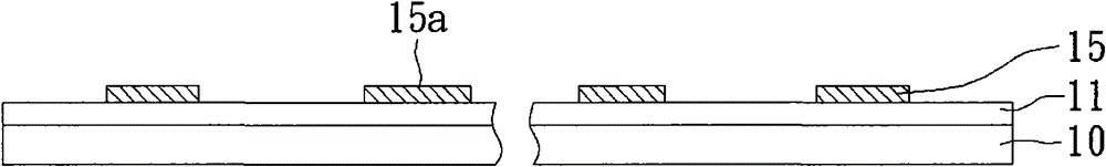
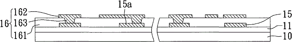
[0070] Next, if Figure 2B As shown, on the metal layer 23 and the core layer 20 of the carrier board 2, a resistance layer 24 is pressed. This resistance layer 24 is mainly pressed on the surface of the metal layer 23, and exceeds the periphery of the metal layer 23. The opening area 244 exposes part of the surface of the metal layer 23 through the exposure and development patterning process. Next, in the opening area 244, for example, use electroplating to form a first circuit layer 25, and ...

Embodiment 3

[0077] The preparation method of this embodiment is substantially the same as that of Embodiment 2, and the differences are described in detail as follows.

[0078] like Figure 2E' As shown, on the surface of the second dielectric layer 261 on the outermost layer of the build-up structure 26, the second circuit layer 262 not only has a plurality of second electrical contact pads 262a, but also has a circuit 262b, and is formed on the surface of the build-up structure 26 An insulating protective layer 27, the insulating protective layer 27 can be, for example, a solder resist layer using green paint, or using dielectric materials commonly used in this field. Wherein, according to the material of the insulating protection layer 27, a plurality of openings 274 can be formed on the insulating protection layer 27 by means of exposure and development or laser ablation (laser ablation), so as to expose the second circuit layer 262 of the outermost layer. Two electrical contact pads...


PUM


Abstract

The invention relates to a coreless layer capsulation substrate and a manufacturing method thereof. The substrate comprises a layer-adding structure which is provided with a first outer side, a second outer side opposite to the first outer side, at least one second dielectric layer which is provided with a first surface facing to the first outer side and a second surface facing to the second outer side, at least one second line layer which is arranged on the second surface of the second dielectric layer, a plurality of conductive blind holes which are arranged in the second dielectric layer, and a first line layer which is embedded and exposed at the first surface of the second dielectric layer on the outermost layer of the first outer layer of the layer-adding structure, wherein the second line layer on the outermost layer of second outer side is provided with a plurality of second electric contact pads; the first line layer is provided with a plurality of first electric contact pads; and the first line layer is electrically connected to the second line layer through the plurality of conductive blind holes on the layer-adding structure. Besides, the manufacturing method provided by the invention is suitable for the technical property of the traditional machine, and can be used for achieving the purposes such as lowering the cost and the like so as to increase the reliability and yield of the capsulation substrate.

Description

technical field [0001] The present invention relates to a method for manufacturing a carrier plate and a coreless layer packaging substrate, in particular to a carrier plate suitable for making a coreless layer package substrate and its manufacturing method, and the coreless layer package made from the carrier plate Substrate manufacturing method. Background technique [0002] With the vigorous development of the electronic industry, electronic products have gradually entered the development trend of multi-function and high performance. In order to meet the packaging requirements of high integration and miniaturization of semiconductor packages for more active and passive components and circuit loading, semiconductor packaging substrates have gradually evolved from double-layer to multi-layer (multi- layer), so that the interlayer connection technology (interlayer connection) can be used in a limited space to expand the available circuit layout area on the semiconductor pac...

Claims


Application Information

Patent Timeline
Patent Type & Authority Patents(China)
IPC IPC(8): H01L21/48H01L23/498
CPCH01L2924/0002
Inventor 江仁宏郑兆孟
Owner UNIMICRON TECH CORP
Why Eureka
Try Eureka