Circular-waveguide slow-wave structure for angularly loading spiral line

A slow-wave structure and helical technology, applied in the field of traveling wave tube amplifier devices, can solve the problems of reduced power and gain of the whole tube, unfavorable equipment miniaturization, and large device operating voltage, so as to reduce the phase velocity and improve the interaction efficiency. , the effect of low operating voltage

Inactive Publication Date: 2011-05-25
UNIV OF ELECTRONICS SCI & TECH OF CHINA
View PDF3 Cites 17 Cited by
  • Summary
  • Abstract
  • Description
  • Claims
  • Application Information

AI Technical Summary

Problems solved by technology

[0005] However, because the relative permittivity ε of the medium r It is limited, and its slow wave ratio cannot be very large. According to the law of energy conservation, the operating voltage of the device is proportional to the phase velocity. Therefore, when the phase velocity is too large, the operating voltage of the device will be too large, which is very unfavorable for the miniaturization of equipment.
In addition, if a material with a large dielectric constant is selected, the coupling impedance will also be severely reduced, resulting in a decrease in the power and gain of the entire tube

Method used


Image

  • Circular-waveguide slow-wave structure for angularly loading spiral line
  • Circular-waveguide slow-wave structure for angularly loading spiral line
  • Circular-waveguide slow-wave structure for angularly loading spiral line

Examples


Embodiment Construction

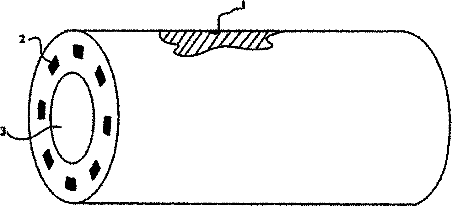
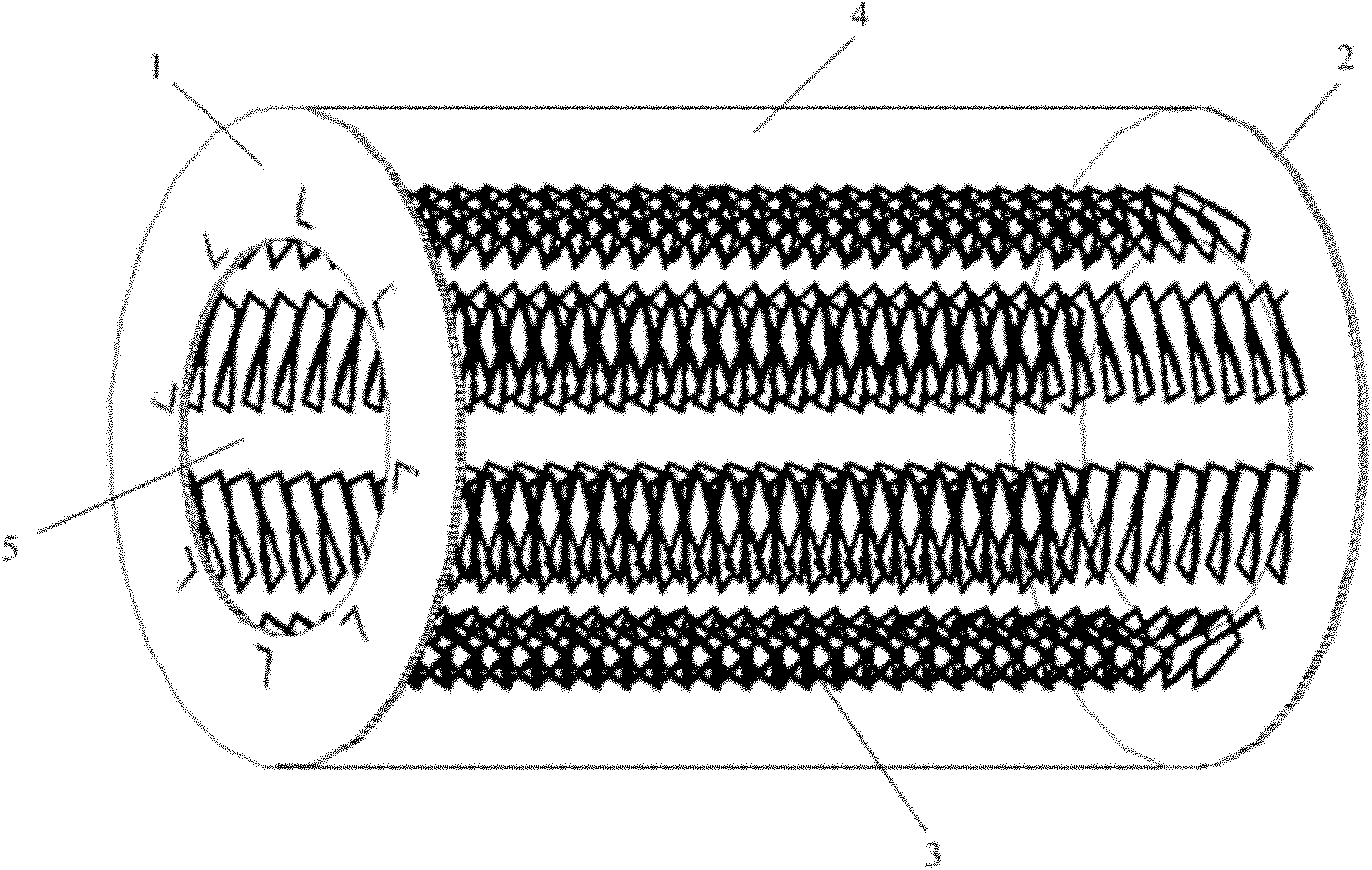
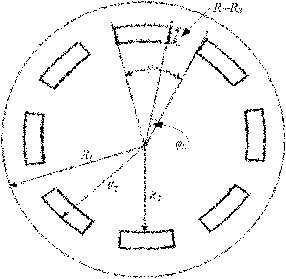
[0017] A circular waveguide slow-wave structure with an angularly loaded helix, such as figure 2 shown, including a radius R 1 A circular waveguide 4, N identical helixes 3 and two outer radii R 1 , the inner radius is R 5 The ring dielectric sheets 1 and 2; two ring dielectric sheets 1 and 2 are respectively fixed on the two end faces of the circular waveguide 4, and N identical helixes 3 are connected between the two ring dielectric sheets 1 and 2 , so that N identical helixes 3 are angularly evenly distributed inside the circular waveguide 4 . More specifically, N identical helixes 3 are angularly evenly distributed in the circular waveguide 4 with an outer diameter R 2 , the inner diameter is R 3 In the circular cylindrical space of , the angular distance between two adjacent helixes 3 is 2π / N, and R 1 2 3 5 ; The hollow parts of the two annular dielectric sheets and the space parts surrounded by all the helixes jointly form the electron injection channel 5 .

[0...


PUM


Abstract

The invention relates to a circular-waveguide slow-wave structure for angularly loading spiral lines, which belongs to the technical field of vacuum electrons and comprises a circular waveguide, N identical spiral lines and two circular-ring medium sheets, wherein the radius of the circular waveguide is R1, the outer radii of the two circular-ring medium sheets are R1, and the inner radii of the two circular-ring medium sheets are R5; the two circular-ring medium sheets are respectively fixed on the two end surfaces of the circular waveguide, and the N identical spiral lines are all connected between the two circular-ring medium sheets, so that the N identical spiral lines are angularly and uniformly distributed inside the circular waveguide; and the hollow parts of the two circular-ring medium sheets and a space part surrounded by all the spiral lines together form an electron-beam passage. The circular-waveguide slow-wave structure can work at short millimeter-wave and terahertz-wave bands, the coupling impedance can be effectively improved, and a dispersion curve is more flat, so that a traveling-wave tube adopting the novel slow-wave structure has higher gain and interaction efficiency, and the larger output power is obtained; and in addition, the phase velocity can be greatly decreased in the invention, accordingly a lower working voltage can be adopted, and the circular-waveguide slow-wave structure is favorable to the miniaturization of devices.

Description

technical field [0001] The invention belongs to the technical field of vacuum electronics and relates to a traveling wave tube amplifier. Background technique [0002] Traveling wave tube is the most important type of microwave source in the field of vacuum electronics technology. It has the characteristics of high power, high efficiency, high gain, broadband and long life. It is widely used in radar, guidance, satellite communication, microwave remote sensing, and radiation measurement. And other fields, its performance directly determines the level of equipment. The core component of a traveling wave tube is a slow wave structure. [0003] With the rapid development of modern electronic technology, my country's aerospace engineering and new generation satellites urgently need a large number of millimeter wave sources with broadband, high efficiency, light weight and small size. However, as the operating frequency increases, especially in the short millimeter wave band or...

Claims


Application Information

Patent Timeline
Patent Type & Authority Applications(China)
IPC IPC(8): H01J23/26
Inventor 魏彦玉刘漾宫玉彬段兆云徐进赵国庆王文祥
Owner UNIV OF ELECTRONICS SCI & TECH OF CHINA
Why Eureka
Try Eureka