Multi-spindle U drill gang spindle box and U drill gang high-speed numerical control drilling machine

A spindle box and spindle technology, which is applied in drilling/drilling equipment, parts of boring machine/drilling machine, boring/drilling, etc. It can solve the problems of not being able to meet high efficiency and high quality, so as to improve the finish of hole processing and extend the Tool durability, good performance results

Inactive Publication Date: 2011-06-15
三门峡合鑫机床有限公司
View PDF5 Cites 12 Cited by
  • Summary
  • Abstract
  • Description
  • Claims
  • Application Information

AI Technical Summary

Problems solved by technology

In the current existing technology, there is no U-drill group formed by combining multiple U-drills at close distances at the same time. For porous workpieces that must be processed by U-drills, they can only be processed one by one. This processing method still cannot meet the requirements. High efficiency and high quality work requirements

Method used


Image

  • Multi-spindle U drill gang spindle box and U drill gang high-speed numerical control drilling machine
  • Multi-spindle U drill gang spindle box and U drill gang high-speed numerical control drilling machine
  • Multi-spindle U drill gang spindle box and U drill gang high-speed numerical control drilling machine

Examples


Embodiment 1

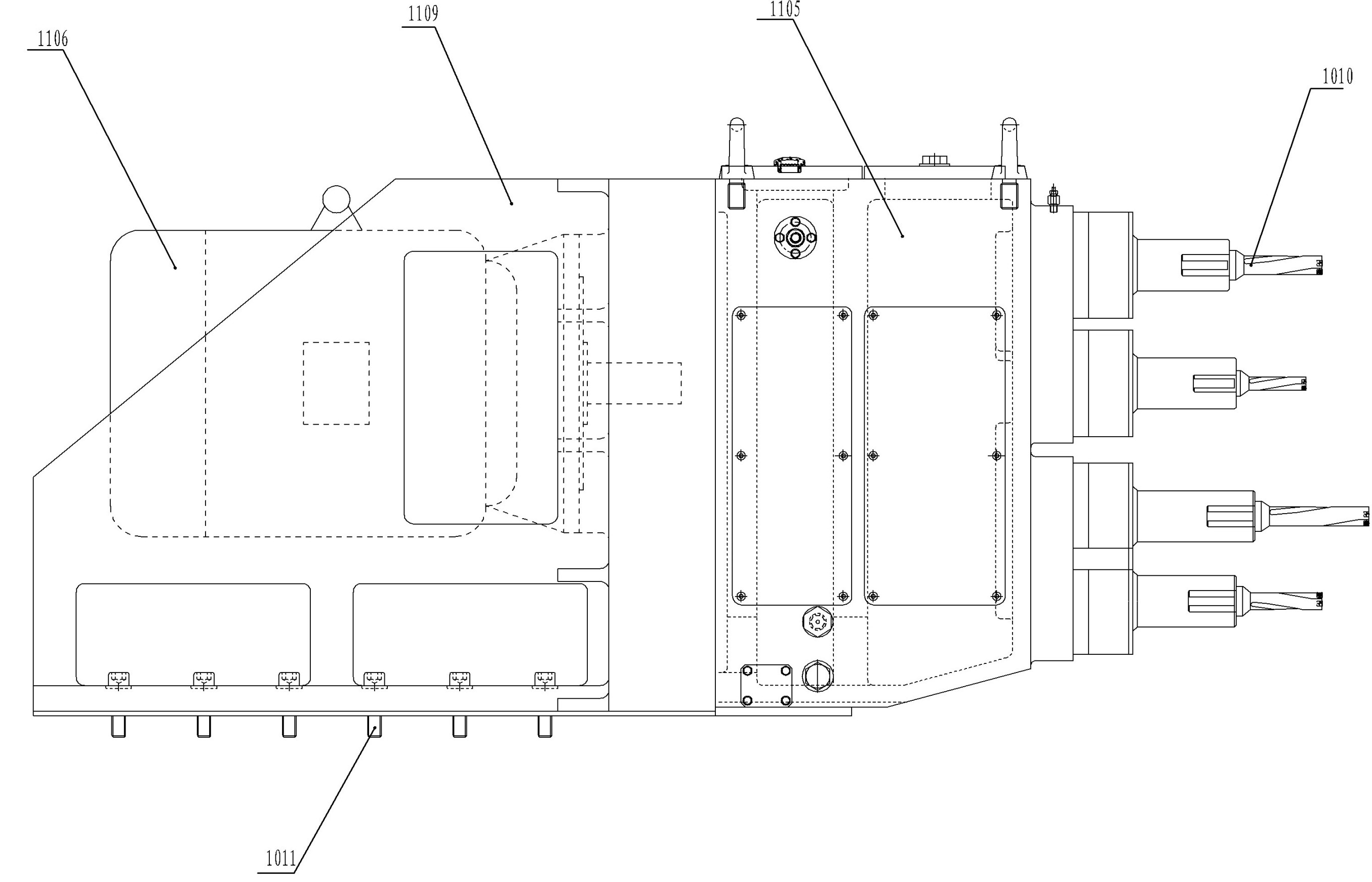
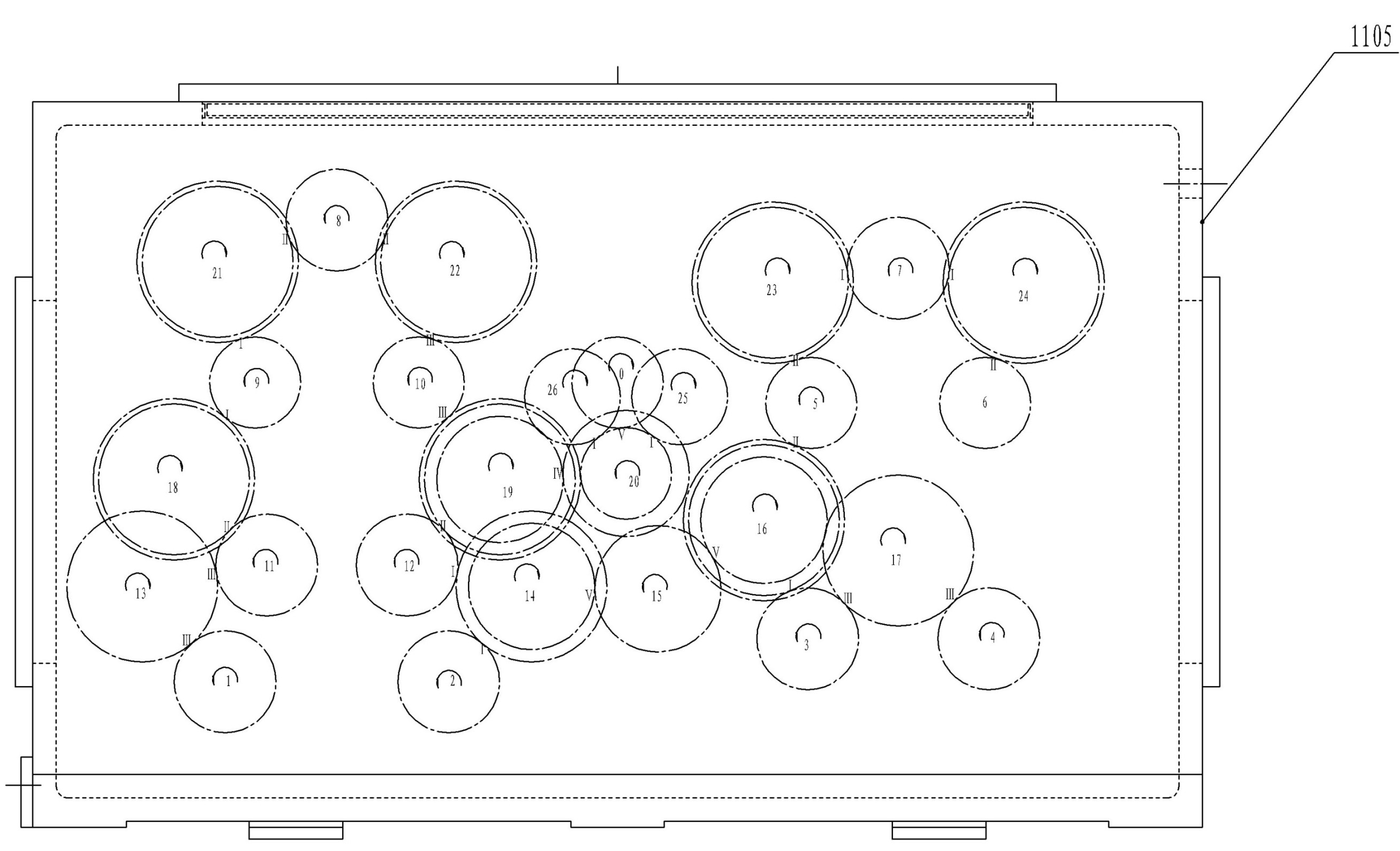
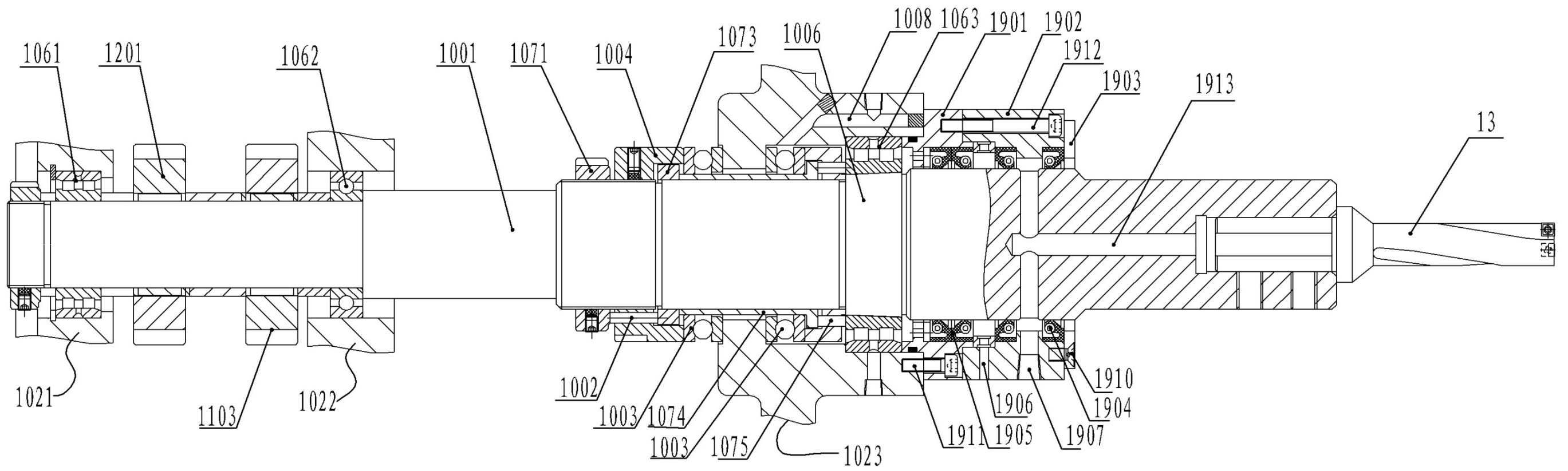
[0027] Embodiment one: see figure 1 — Figure 7 , a multi-axis U drill group spindle box, the spindle box includes a box body, a bracket fixed on the drilling machine is arranged on the rear side of the box body, the motor is horizontally fixed on the bracket, and the output shaft of the motor is inserted into the inside of the box body as The main transmission shaft is represented by the O axis in the figure. Wherein the box body is vertically provided with three layers of support walls respectively, wherein the support walls on both sides outside can be the side walls of the box body, and a plurality of U drill spindles are horizontally installed in the shaft holes of each support wall through three corresponding bearings respectively, In the figure, the support wall close to the motor is labeled 1021, the middle support wall is 1022, and the support wall close to the drill bit is 1023. The support structure of multiple support walls and multiple bearings can improve the st...

Embodiment 2

[0078] Embodiment 2: Referring to the figure, a U-drill group high-speed CNC drilling machine includes a machine base, a horizontal slide table (a mechanical slide table in this embodiment), a longitudinal slide table (a numerical control slide table in this embodiment), and a water cooling mechanism And the chip catcher also includes the headstock of the multi-axis U drill group described in the first embodiment. The bracket of the spindle box of the multi-axis U drill group is fixed on the horizontal slide table, and the slide between the horizontal slide table and the machine base is slidably connected by guide wheels and guide rails. There is a threaded rod, and the threaded rod is matched with the nut bushing at the bottom of the headstock support of the multi-axis U drill group. Through the rotation of the drive motor, the horizontal sliding table can be translated to a designated position as required. In this embodiment, the driving motor of the horizontal slide table i...


PUM


Abstract

The invention relates to a multi-spindle U drill gang spindle box and a U drill gang high-speed numerical control drilling machine. The spindle box comprises a box body, a bracket and a motor, wherein at least three layers of supporting walls are arranged vertically in the box body; more than three U drill spindles are respectively arranged in an axle hole of each supporting wall horizontally through a corresponding roller bearing; meanwhile, two side walls of the axle hole of each U drill spindle are respectively provided with a thrust bearing; a cooling mechanism is arranged on the outer end face of the supporting wall closest to a drill bit or the side wall of the box body; the spindle box also comprises auxiliary spindles driven by the U drill spindles; and each spindle and each auxiliary spindle are matched, meshed and in transmission connection through a corresponding layer gear. The drilling machine comprises a machine tool base, a transverse slide table, a longitudinal slide table, a water cooling mechanism, a scrap receiver and the multi-spindle U drill gang spindle box. The invention realizes multi-spindle U drill high-speed high-efficiency drilling processing, can ensure positional accuracy of holes, improves hole processing finish, prolongs the service life of a tool, reduces processing cost in a different form, improves the processing efficiency and the durabilityof the tool, and is innovation in the field of modern high-efficiency special machine tools.

Description

technical field [0001] The invention relates to a high-efficiency multi-axis drilling machine tool, in particular to a multi-axis U-drill group spindle box and a U-drill group high-speed numerical control drilling machine. Background technique [0002] In the traditional machining of hole systems, twist drills and group drills can be widely used in radial drills, vertical drills, multi-spindle combined drilling machines, and even hand electric drills because of their simple structure and low cost. However, with the rapid development of modern mechanical processing to high-speed, high-efficiency, and composite processing, the drilling of composite materials and materials that are difficult to process such as high hardness and high strength has been fundamentally changed due to the invention of the U drill. A twist drill is a tool that drills a circular hole in a workpiece by rotating it relative to a fixed axis. Compared with twist drills, the advantages of U drills are: 1. ...

Claims


Application Information

Patent Timeline
IPC IPC(8): B23B47/02B23Q5/04B23B39/16
Inventor 徐长群王素琴兀治军葛卫华蔡帅强
Owner 三门峡合鑫机床有限公司
Why Eureka
Try Eureka