Multilayer electromagnetism modulating structure and preparation method thereof

An electromagnetic and artificial electromagnetic technology, which is applied in the deposition process and alignment overlay process to realize the preparation of the structure, in the field of spin coating, can solve the problems of limited modulation effect, weakened modulation effect, and reduce the distribution density of related units, so as to avoid serious problems. Effect of loss, increase of modulability

Inactive Publication Date: 2011-06-29
INST OF PHYSICS - CHINESE ACAD OF SCI
View PDF1 Cites 17 Cited by
  • Summary
  • Abstract
  • Description
  • Claims
  • Application Information

AI Technical Summary

Problems solved by technology

This kind of modulation structure is a great breakthrough compared with the modulation structure of only one sub-wavelength unit in the past, but the modulation effect is still limited. At the cost of distribution density, its modulation effect is greatly weakened
In addition, a similar combined modulation function can also be achieved by superimposing multiple materials with sub-wavelength metal structures, such as literature 2, "Three-dimensional multilayer metal pillar-aperture resonator structure realized by deep X-ray exposure" (Towards three-dimensional and multilayer rod-split-ring metamaterial structures by means of deep x-ray lithography), contained in "Applied Physics Letter", 2007, Vol 90, 254106, but the so-called three-dimensional structure in this document is essentially to combine multiple single The layer structure is stacked together, including multiple substrates, so the transmittance of the combined material is also greatly reduced, and the distance between the layers is relatively long (relative to the wavelength), and the subwavelength metal between the layers The relative position of the array also has a certain randomness due to the simple stacking, so this three-dimensional modulation structure also has relatively large defects

Method used


Image

  • Multilayer electromagnetism modulating structure and preparation method thereof
  • Multilayer electromagnetism modulating structure and preparation method thereof
  • Multilayer electromagnetism modulating structure and preparation method thereof

Examples


Embodiment 1

[0055] For electromagnetic waves of different wavelengths to be modulated with target wavelengths, corresponding substrate material layers, medium intermediate layers, and medium covering layers with good transmission characteristics should be selected. For example, for ultraviolet rays with a target wavelength of 200nm-400nm, fluorinated Lead and other materials; for visible light with a target wavelength of 390nm-770nm, materials such as quartz, glass or PET polymers can be used; for infrared rays with a target wavelength of 750nm-1000um, iron-doped zinc selenide infrared transparent ceramics can be used Or JGS3 infrared quartz glass and other materials; for the terahertz electromagnetic wave whose target wavelength to be modulated is 300um-1mm, materials such as silicon, polytetrafluoroethylene plastic or polyimide resin can be used; for the target wavelength to be modulated is 2mm-1mm For microwave ovens, materials such as polypropylene plastics can be used. In this embodi...

Embodiment 2

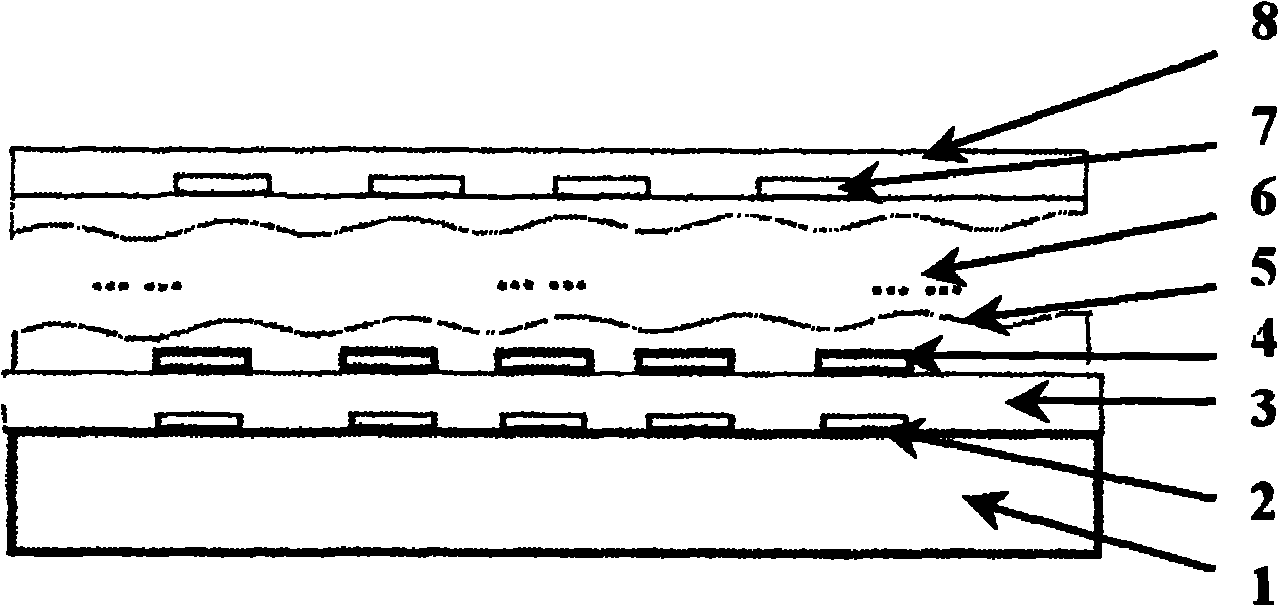
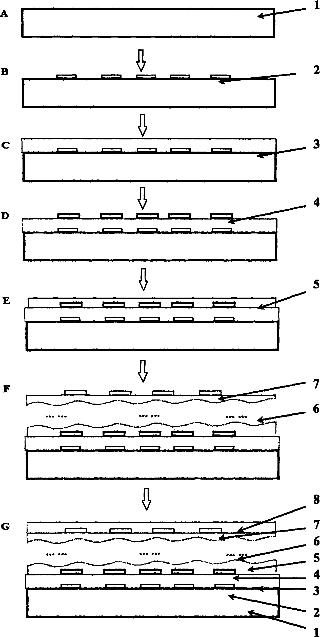
[0065] The preparation of a double-layer combined terahertz electromagnetic wave modulation structure with a double-layer antisymmetric split resonator ring metal structure array on a silicon substrate includes the following steps:

[0066] 1) On an 800 micron thick silicon substrate ( figure 2 A layer of UV photoresist S1813 is spin-coated on the middle A, and the mask plate with the split resonant ring array pattern and four sets of pattern alignment marks is exposed and developed through the ultraviolet exposure system, so that the split resonant ring array and the pattern The alignment marks are transferred to the photoresist, where the split resonant ring unit has a side length dimension of 45 microns, a period length of 60 microns, and an array size of 8 mm x 8 mm;

[0067] 2) Deposit a layer of chromium metal with a thickness of 5 nm and metal gold with a thickness of 100 nm as a transition layer on the silicon substrate treated in step 1) by using a thermal evaporatio...

Embodiment 3

[0072] For the artificial electromagnetic modulation structure of the multi-layer combination in which the electromagnetic waves near the wavelength of 2 microns and 1.5 microns are compounded and modulated at the same time, the realization steps are as follows:

[0073] 1) Select an ITO glass substrate that is transparent to near-infrared electromagnetic waves; spin-coat a layer of electronic resist PMMA on the ITO substrate, use electron beam direct writing exposure and development, and first form a unit length of 300nm on the PMMA, Composed of U-shaped structural units with a line width of 60nm, a period length of 500nm, and an area of ​​0.8mm×0.8mm, the square first unit structure array pattern forms four cross-shaped patterns near the four corners of the array at the same time alignment marks;

[0074] 2) Utilize electron beam evaporation to deposit 50nm thick metallic silver on the surface of the sample prepared in step 1), then immerse the sample in an acetone solution ...


PUM

PropertyMeasurementUnit
thicknessaaaaaaaaaa
thicknessaaaaaaaaaa
wavelengthaaaaaaaaaa

Abstract

The invention relates to a multilayer manual electromagnetism modulating structure and a preparation method thereof. In the structure, a plurality of layers of accurately aligned metal subwavelength structures, a medium interlayer and a covering layer form a multi-layer combination to realize various specific electromagnetic modulation functions of frequency selection, filtration, refection reduction, rotation, special refraction and the like. In the preparation method of the multilayer electromagnetism modulating structure, spinning or depositing and accurate alignment overlay processes are used to realize interlayer accurate alignment. When the manual electromagnetic structure of the multilayer laminar structure prepared by the preparation method is used, the electromagnetic coupling between layers can be realized by the accurately aligned metal structures, and the modulating capability of the structure for electromagnetic valves of specific wavelength can be increased.

Description

technical field [0001] The present invention relates to a metal sub-wavelength structural unit array utilizing multi-layer combination, which is an artificial structure that realizes specific modulation for specific wavelength electromagnetic waves, and involves the application of spin coating, deposition process and alignment overlay process to realize the structure Preparation. Background technique [0002] Controlling the propagation of electromagnetic waves by using sub-wavelength-sized artificial materials with special electromagnetic propagation properties is the focus of current research frontiers in materials physics. For electromagnetic waves of a specific wavelength, the electromagnetic response characteristics of a sub-wavelength metal structure with a size of 1 / 3 to 1 / 30 of the wavelength can be used to achieve specific electromagnetic signal modulation, and the usual modulation structure consists of only An array of sub-wavelength metal structures and their sub...

Claims


Application Information

Patent Timeline
Patent Type & Authority Applications(China)
IPC IPC(8): G02F1/01G03F7/00
Inventor 夏晓翔杨海方顾长志张异光
Owner INST OF PHYSICS - CHINESE ACAD OF SCI
Why Eureka
Try Eureka