
Device for continuously separating gas hydrate
A gas hydrate and hydrate technology, applied in solid separation devices, gas and liquid fields, can solve the problems of increased investment cost, operation management and maintenance costs, long processing time, poor separation effect, etc. The effect of large processing capacity and easy installation
- Summary
- Abstract
- Description
- Claims
- Application Information
AI Technical Summary
Problems solved by technology
Method used
Image

Examples
Embodiment Construction
[0016] Below in conjunction with accompanying drawing and embodiment the present invention will be further described:
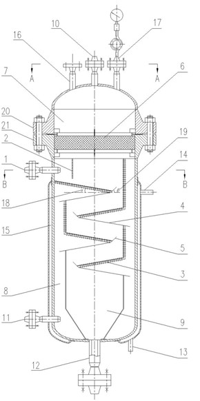
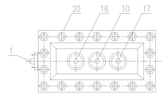
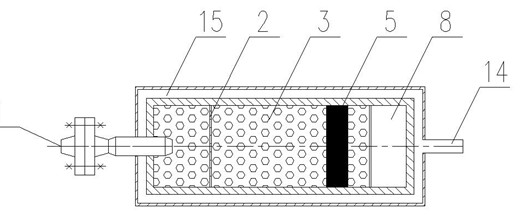
[0017] like figure 1 As shown, a device for continuous separation of gas hydrates consists of an upper box and a lower box, the box is connected by an upper flange 20 and a lower flange 21; the upper box is a gas collection chamber 7, and its The top is arched, the upper end is provided with a separation gas outlet 10, a safety valve port 16 and a pressure gauge port 17, and the lower part is provided with a wire mesh demister 6; the lower box is cuboid, and the upper part is provided with a hydrate slurry inlet 1, The cross-section of the hydrate slurry inlet 1 is circular, and the end is provided with a vertical flow equalizer 2. A sieve plate 3 is provided at a distance of 8 to 20 mm from the bottom of the flow equalizer 2. The three sides of the sieve plate 3 are connected to the lower box. The sieve plate 3 is alternately connected with the drainage pla...
PUM
 Abstract
Description
Claims
Application Information