

Tubular photobioreactor and system and method for culturing microalgae cells
A technology of photobioreactor and microalgae cells is applied in the field of systems for cultivating microalgae cells, which can solve the problems of complex structure, difficulty in ensuring the illumination of microalgae cells, and high manufacturing cost, so as to improve the yield, improve the utilization rate of light energy, simple structure
- Summary
- Abstract
- Description
- Claims
- Application Information
AI Technical Summary
Problems solved by technology
Method used
Image

Examples
Embodiment 1
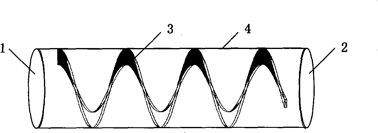
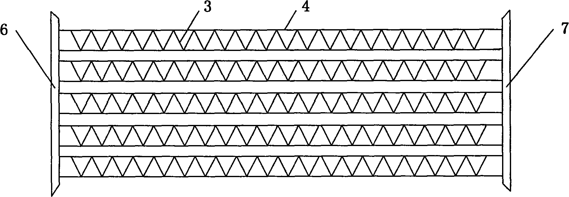
[0038] Spirulina was cultivated outdoors under natural light. Build a culture system in parallel tubular photobioreactors, such as image 3 As shown, the tube-type photobioreactor used is placed horizontally, and the manufacturing material is a glass circular tube with an inner diameter of 50 mm and a length of 10 m. Every 10 circular tubes 4 are arranged side by side, one end is connected with the main pipe 6 of the culture solution inlet, and the other end is connected with the main pipe 7 of the culture solution outlet, forming a group. Put the spiral baffle made of polyethylene material in advance into the tubular photobioreactor, the pitch of the spiral baffle is 50mm, the width is 10mm, and the thickness is 2mm. The helical baffle runs the entire length of the pipe, except for the parts where the connecting pipe fittings are to be installed at both ends of the pipe.
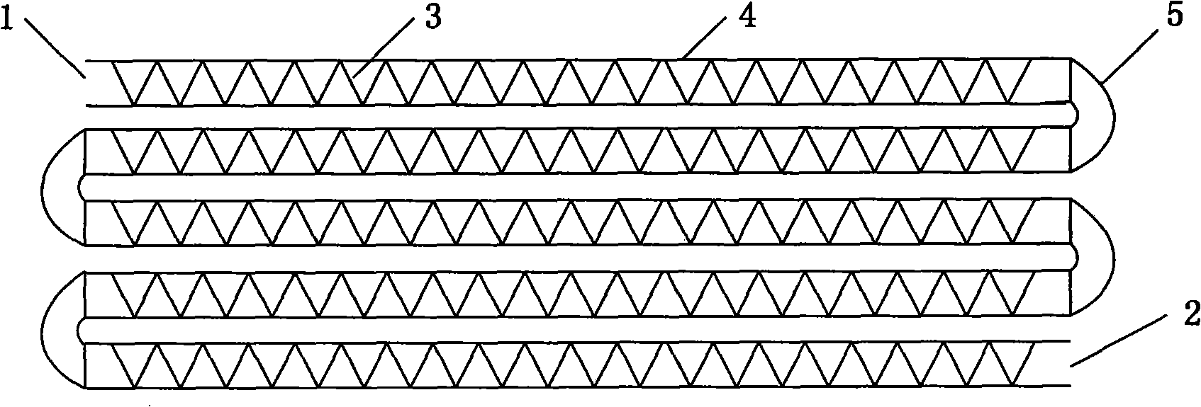
[0039] Such as Figure 5 As shown, the system for cultivating microalgae cells includes 2 groups of t...
Embodiment 2
[0049] Spirulina was cultivated under natural light. Other conditions are the same as in Example 1, except that the width of the built-in spiral baffle is 5 mm.
[0050] The culture process lasted for 30 days, and the volumetric productivity of Spirulina was about 2.0g / L.d. It is higher than the volumetric yield (1.1g / L.d) under the same culture conditions in the tubular photobioreactor without spiral baffles, indicating that the light energy utilization rate of the microalgae cells is significantly improved.
Embodiment 3
[0052] Spirulina was cultivated under natural light. Other conditions are the same as in Example 1, except that the width of the built-in spiral baffle is 15 mm.
[0053] The culture process lasted for 30 days, and the volumetric productivity of Spirulina was about 2.4g / L.d. It is higher than the volumetric yield (1.1g / L.d) under the same culture conditions in the tubular photobioreactor without spiral baffles, indicating that the light energy utilization rate of the microalgae cells is significantly improved.
PUM
| Property | Measurement | Unit |
|---|---|---|
| The inside diameter of | aaaaa | aaaaa |
| Length | aaaaa | aaaaa |
| Volumetric yield | aaaaa | aaaaa |
Abstract
Description
Claims
Application Information