Solar 'finned heat pipe'

A fin type, solar energy technology, applied in the field of solar energy application, can solve the problems of low actual thermal efficiency, insufficient hot water supply, and fewer users, and achieve the effects of excellent heat collection performance, easy mass production, and improved efficiency.

Inactive Publication Date: 2011-07-27
南京绿盾电气设备有限公司
View PDF0 Cites 1 Cited by
  • Summary
  • Abstract
  • Description
  • Claims
  • Application Information

AI Technical Summary

Problems solved by technology

Because the thickness of the metal heat-absorbing coating on the outer surface of the inner tube is limited by the metal spraying process, just like the process problems in the thickness of the electroplating layer, the skin will peel off when the layer thickness is too large, so the current metal heat-absorbing coating is aimed at The obvious light transmission phenomenon can be seen in the visual field, but it cannot be solved, so it is unlikely to further increase the α value.
[0008] Due to the "isothermal effect" of the heat pipe, it has the advantages of strong low-density energy collection ability and high heat transfer rate, and has no disadvantages of energy retention in the pipe. It is especially suitable for use in the field of solar energy, but due to the existing solar "water copper heat pipe" Many technical deficiencies lead to the fact that the actual thermal efficiency is lower than that of the "vacuum glass" collector tube solar water heater
Because the thermal efficiency of existing solar water heaters is low, and because the roof area is limited, the number of users that the central heating system can provide is reduced, and the hot water supply is insufficient in winter. The stipulation that solar water heaters must be installed in buildings below 12 floors can only be enforced in some areas.

Method used


Image

  • Solar 'finned heat pipe'
  • Solar 'finned heat pipe'
  • Solar 'finned heat pipe'

Examples


Embodiment Construction

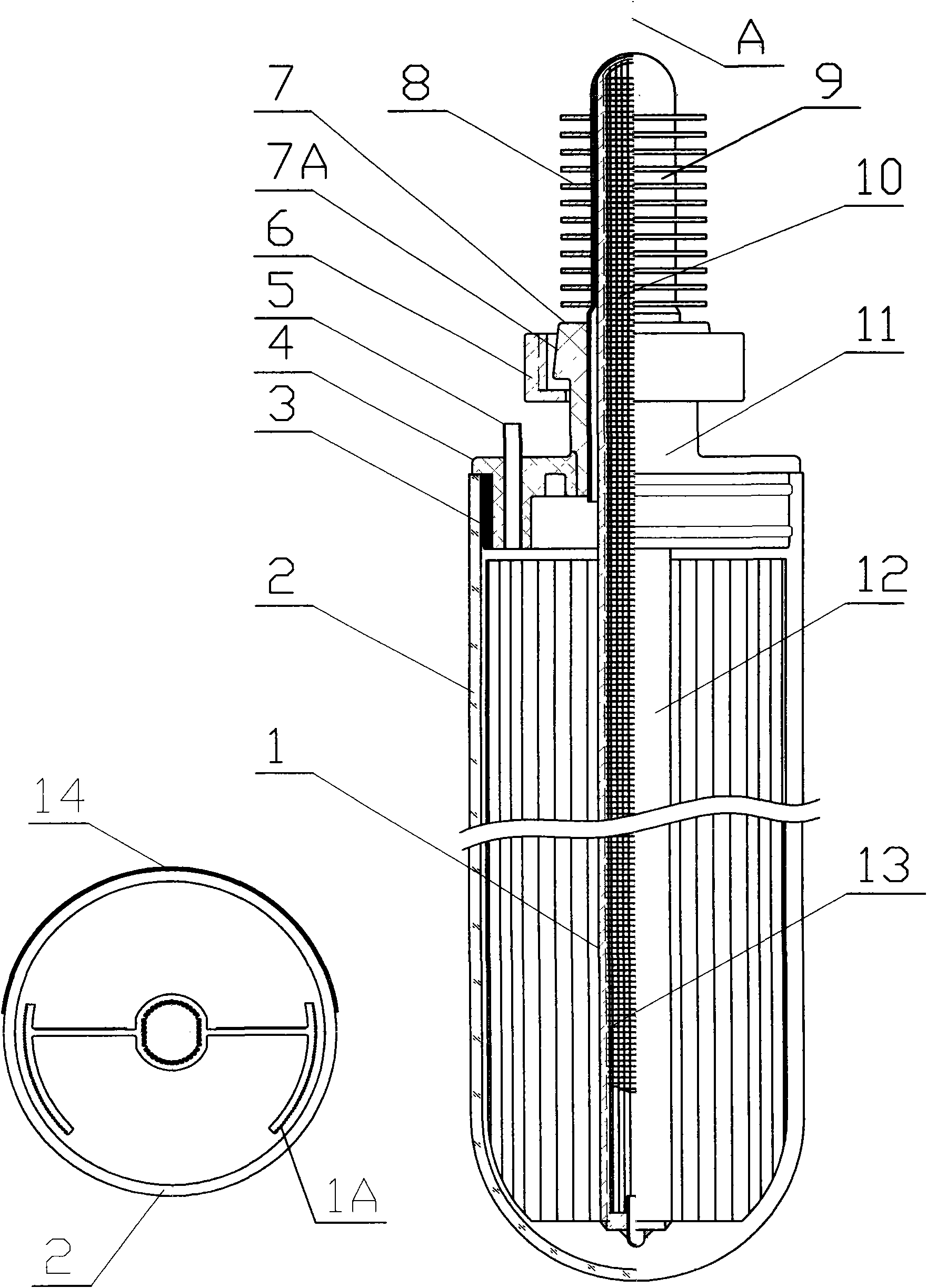
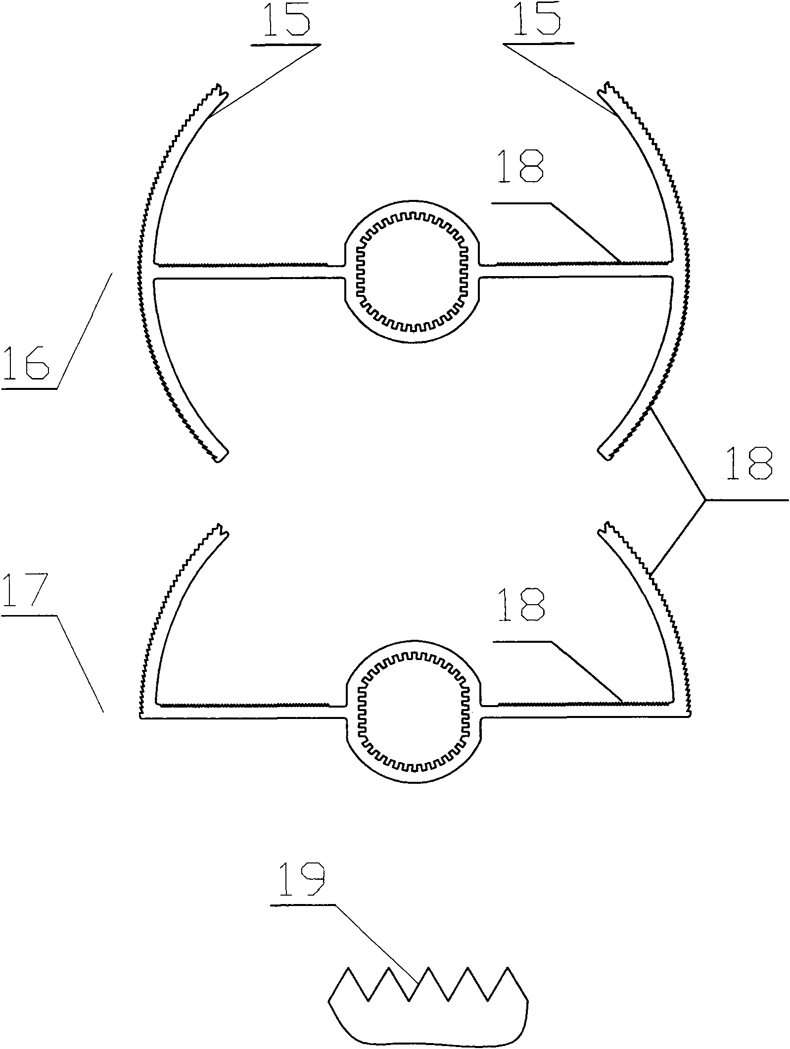
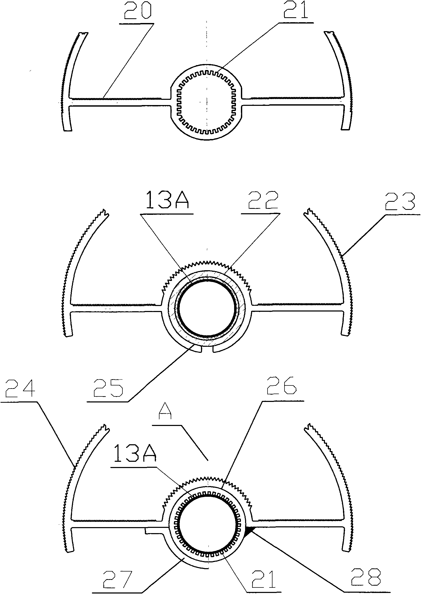
[0033] See attached figure 1 , the solar energy " finned heat pipe " of the present invention, its structure mainly comprises the arc-shaped sail 15 (attached) that is symmetrical with the axial center figure 2 ) composed of sail-shaped finned heat pipe 1, single-layer transparent heat preservation pipe 2, rubber sealing ring 3, exhaust pipe 5, lock nut 6, condensing fin 8, condensing copper pipe 9, double sealing cover 11, reflective film 14, the condensing copper pipe 9 and the exhaust pipe 5 are inlaid on the double sealing cover 11 when the double sealing cover 11 is injected. On the condensing copper tube 9, the condensing copper tube 9 inlaid on the double sealing cover 11 is installed on the condensing section 10 of the sail-shaped finned heat pipe 1, and the rubber sealing ring 3 is installed on the seal on the double sealing cover 11 On the gas cover 4, the gas sealing cover 4 equipped with the rubber sealing ring 3 (select the attached figure 1 or choose to atta...


PUM


Abstract

The invention discloses a solar 'finned heat pipe'. A heat pipe fin of the solar 'finned heat pipe' serves as an irradiated surface for directly collecting solar energy; a state that the heat pipe only serves as an intermediate heat transfer tool in the prior art is changed, so radiation energy collected by the heat pipe fin can be directly transmitted to stored water by fully taking advantage of high capacity of the heat pipe of collecting and transmitting low-density energy; and a temperature gradient between the fin and the stored water can be reduced to less than or equal to 5 DEG C, and an 'isothermal effect' of the heat pipe can be achieved. An effective thermal-collecting area is increased by more than ten technical measures capable of obviously improving the thermal-collecting efficiency, such as a windsurfing fin, a heat-absorbing groove, reflection and heat concentration, a matt black body and the like, so a radiation absorption ratio alpha is above 96 percent, and an effect of 67 percent of actual thermal-collecting efficiency is achieved; and compared with the 33.5 percent of actual thermal-collecting efficiency of a 'vacuum glass' thermal-collecting tube, the actual thermal-collecting efficiency is doubled, and the requirement that a winter water temperature of a balcony wall-mounted water heater is higher than 45 DEG C is met. The invention has the advantages of rational structural design, simple technology, low cost, high reliability, high thermal-collecting efficiency, good thermal-collecting performance in winter and the like; and the solar 'finned heat pipe' is convenient to arranged and use, is applicable to various areas and can provide high-temperature high-pressure hot water for industrial needs or power generation.

Description

technical field [0001] The invention relates to a solar "heat pipe", in particular to a finned heat pipe which can obviously improve the utilization rate of solar radiation energy, and belongs to the field of solar energy application. Background technique [0002] The prior art solar "water copper heat pipe" heat collecting pipe is actually a "heat pipe type light-to-heat conversion system". Its structure mainly includes water copper heat pipe, plastic cover and double-layer "vacuum glass" heat collecting pipe coated with metal heat-absorbing coating between layers. , Condensation section with a length of 50-100m (attached Figure 5 ), the center of the plastic cover is provided with a hole through which the heat pipe can pass, and the heat collecting section of the water copper heat pipe passes through the plastic cover and is installed in the "vacuum glass" heat collecting tube. The condensing section of the water copper heat pipe is inserted into the installation hole of...

Claims


Application Information

Patent Timeline
IPC IPC(8): F24J2/32F24J2/46F24J2/50F28D15/02F28F1/12F24S10/95
CPCY02E10/44F24S10/45F24S10/95Y02P80/10Y02P80/20
Inventor 李光华谢河
Owner 南京绿盾电气设备有限公司
Why Eureka
Try Eureka