Optical engine for projector

An optical engine and projector technology, applied in the field of projection display, can solve the problems of complex optical structure, poor spot shaping and uniform light effect, large light energy loss, etc., to achieve uniform energy distribution, miniaturization of the whole machine, and high light energy. The effect of utilization

Inactive Publication Date: 2011-08-10
UNIV OF ELECTRONICS SCI & TECH OF CHINA
View PDF5 Cites 17 Cited by
  • Summary
  • Abstract
  • Description
  • Claims
  • Application Information

AI Technical Summary

Problems solved by technology

[0010] In order to overcome the deficiencies of existing projectors such as complex optical structure, large loss of light energy, and poor effect of spot shaping and homogenization, the present invention provides an optical engine for projectors.

Method used


Image

  • Optical engine for projector
  • Optical engine for projector
  • Optical engine for projector

Examples


no. 1 approach

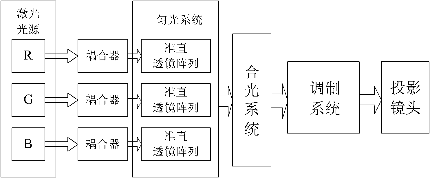
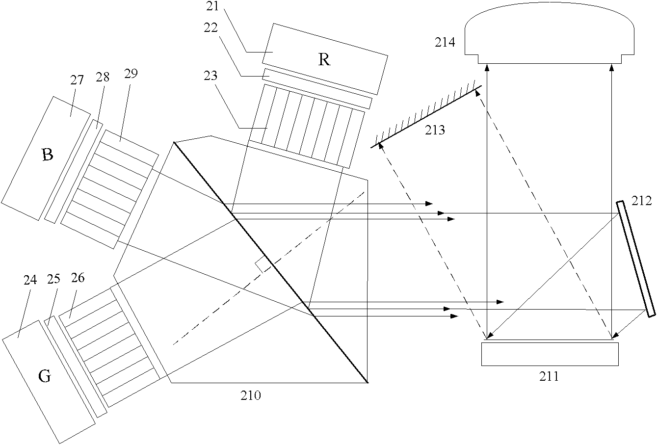
[0031] The first embodiment of the present invention is applicable to the optical engine of a monolithic DMD or LCoS optical modulator. like figure 2 As shown, the optical engine includes: RGB tricolor laser light sources 21, 24, 27, three beam couplers 22, 25, 28, three collimating lens arrays 23, 26, 29, and a Wollaston light combining prism 210 , light modulator components 211 , 212 , 213 , projection lens 214 .

[0032] The light source adopts laser light source, providing RGB three primary colors. A color uses at least one laser. The driving method of the light source adopts the time-mixing method, that is, the three RGB light sources sequentially emit sequential light pulses within one frame time, and the monochrome pulse width is divided according to the white balance. Full color display.

[0033] The beam coupler is used to realize the optical connection between the laser light source and the collimating lens array. The connection method between the monochromatic...

no. 2 approach

[0046] The second embodiment of the present invention is applicable to the optical engine of a monolithic DMD or LCoS optical modulator. The second embodiment is improved on the basis of the first embodiment. The improvement is that the X prism is used instead of the Wollaston prism to combine light. Such as Figure 7 As shown, the X prism 81 is formed by splicing the right angles of four right-angle prisms. R light: full transmission of ab surface and cd surface; G light: total reflection of ab surface, full transmission of cd surface; B light: total reflection of cd surface, full transmission of ab surface. The synthesized light is emitted through the bd surface and projected to the light modulator. Its characteristic is that there is no need to consider the polarization of the laser, and the device for obtaining the polarization and the device for shaping the combined light output end are removed, and the structure is further simplified.

no. 3 approach

[0048] The third embodiment of the present invention is applicable to the optical engine of a monolithic DMD or LCoS optical modulator. The third embodiment is improved on the basis of the first embodiment and the second embodiment. The improvement is that the light-combining prism adopts three-component color mirrors. Such as Figure 8 As shown, 91 mirrors fully reflect B light; 92 mirrors fully transmit B light, fully reflect G light; 93 mirrors fully transmit B and G light, and fully reflect R light. The light is combined by 93 mirrors and projected to the modulator. Compared with the X prism, the reflector has a simpler structure, less optical path loss, higher utilization rate of light energy, and lower manufacturing cost.


PUM


Abstract

The invention relates to an optical engine for a projector, belonging to the technical field of projection display. Three light beam couplers respectively output three groups of array light by processing laser light generated by an RGB (three primary colors: red, green and blue) laser light source; a light-equaling system comprises three collimation lens arrays; each collimation lens array consists of gradient reflective index lens units with a quarter of pitch of optical length; the three groups of array light are respectively output by the three collimation lens arrays to form three groups of parallel light with even energy distribution; and the parallel light can be merged by a merging and modulating system, and then can be output to a projection lens. In the optical engine, the light-equaling system adopts the collimation lens arrays consisting of the gradient reflective index lens units and can simultaneously realize light equaling, reshaping and collimation; the energy of emergent light spots of the light-equaling system are equally distributed, so as to realize higher utilization rate of light energy; simultaneously, the light-equaling system has the characteristic of a simple structure, is beneficial to reducing the volume of the optical engine and realizes miniaturization of a complete machine. A light merging system can adopt a Wollaston prism; based on related principles of crystal optics and polarization optics, the light merging structure is innovated, so as to further increase the utilization rate of light energy.

Description

technical field [0001] The invention belongs to the technical field of projection display, and relates to an optical engine for a projector, in particular to an optical engine for a projector based on a laser light source. Background technique [0002] Generally, the optical engine of a projector includes a light source, a light uniform system, a light combination system, a modulation system, and a projection lens. Among them, the light source and the uniform light system are the main factors that determine the light energy utilization rate of the optical engine, and the light uniform system is the main factor that determines the size of the optical engine. At present, projector optical engines are mainly divided into three types: Digital Light Process (DLP), Liquid Crystal on Silicon (LCoS), and Liquid Crystal Light Valve (LCLV) according to different spatial modulation technologies. kind. The light source generally adopts ultra-high pressure mercury lamp (Ultra High Perf...

Claims


Application Information

Patent Timeline
Patent Type & Authority Applications(China)
IPC IPC(8): G02B27/18G02B27/09G02B3/00G02B27/10G03B21/00
Inventor 祁康成芮大为林祖伦王小菊曹贵川陈文彬
Owner UNIV OF ELECTRONICS SCI & TECH OF CHINA
Why Eureka
Try Eureka