Redox flow battery system

A liquid flow battery and liquid flow technology, which is applied in the direction of fuel cells, secondary batteries, fuel cell additives, etc., can solve problems such as difficult power output, improve utilization rate, improve charge and discharge performance, and reduce leakage current Effect

Active Publication Date: 2011-08-10
DALIAN RONGKE POWER
View PDF3 Cites 37 Cited by
  • Summary
  • Abstract
  • Description
  • Claims
  • Application Information

AI Technical Summary

Problems solved by technology

However, the power generation of solar energy and wind energy varies significantly with the change of day and night, and it is difficult to maintain a stable powe

Method used


Image

  • Redox flow battery system
  • Redox flow battery system
  • Redox flow battery system

Examples


Embodiment 1

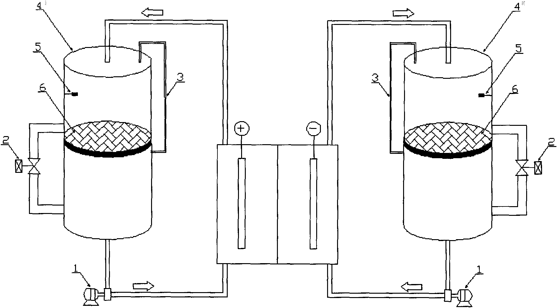
[0025] This redox flow battery system includes a flow battery or a flow battery pack, a positive electrolyte storage tank, and a negative electrolyte storage tank, and the positive electrolyte storage tank is separated into separate parts by a separator. Two spaces for storing electrolytes, and the space for storing electrolytes separated from each other are connected through pipelines, and valves are set on the connecting pipelines; one of the spaces for storing electrolytes is connected to the flow battery or liquid flow battery through pipelines. The positive electrode material inlet of the flow battery pack is connected, and another space for storing electrolyte is connected with the positive electrode material outlet of the flow battery or the flow battery pack through pipelines; Two open spaces for storing electrolyte, and the separate spaces for storing electrolyte are connected through pipelines, and valves are set on the connecting pipelines; one of the spaces for stor...

Embodiment 2

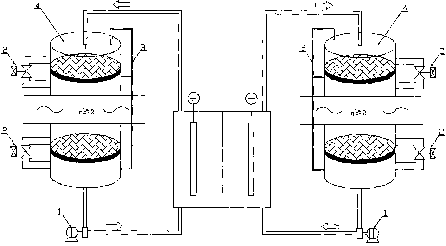
[0030] Such as figure 2 As shown, the difference with the structure of Embodiment 1 is that in this system structure, the number of spaces separated by each pole liquid storage tank is ≥ 3, and the conduction condition between each two spaces is the same as that of Embodiment 1. The difference The reason is that when two adjacent spaces are connected, the remaining spaces are in an isolated state. This operation mode can completely cut off the main circuit of the electrolyte during the charging and discharging process of the battery, avoiding the generation of leakage current.

Embodiment 3

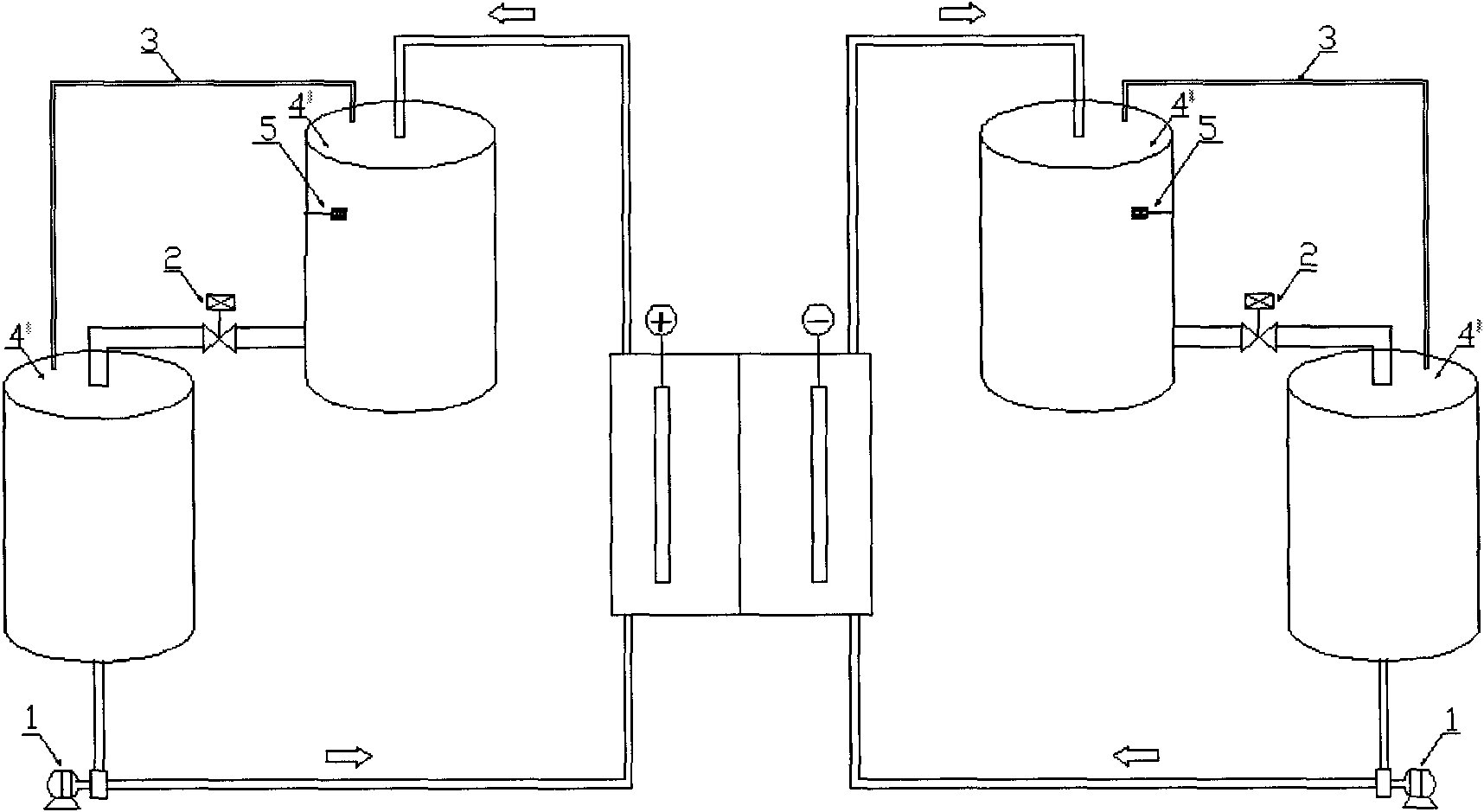
[0032] The specific system structure is composed of image 3 As shown, the difference with the structure of Embodiment 1 is that each pole in this system structure is composed of two liquid storage tanks, and there is a positioning difference when placed in space. When the liquid level meets the conduction condition in Embodiment 1 Valve 2 opens automatically, relies on the gravity field to automatically discharge, and the valve automatically closes after the discharge is completed.


PUM


Abstract

The invention relates to a novel battery system which can reduce leakage current of a redox flow battery and improve the charge-discharge performance of the battery. Each of a positive pole liquid storage tank and a negative pole liquid storage tank is completely isolated into an upper part and a lower part by a partition plate respectively. Firstly, positive pole electrolyte flows from a positive pole pump, flows through the battery and flows back to the upper half part of the positive pole liquid storage tank, when liquid level achieves a liquid level induction device, a valve is opened automatically, the valve is closed automatically after completing discharge of the electrolyte, the circulation is performed in such a way, and a pressure balancing pipe is shown in the figure. In a similar way, the operation way on the side of a negative pole is as that of a positive pole. By adopting the method, a main loop of the electrolyte above 90% of time is in cut-off state, and the leakage current can be further reduced (when multiple storage tanks and multiple spaces are adopted, the leakage current of the main loop can be cut off by 100%). Simultaneously, by adopting the intermittent-like charge-discharge way, the impacts of differential concentration polarization can be reduced, and the SOC (state of charge)/SOD (state of discharge) state of the redox flow battery can be improved.

Description

technical field [0001] The invention relates to the field of chemical energy storage by electrochemical reaction, in particular to a large-scale energy storage system of a redox flow battery. Background technique [0002] With the rapid development of the national economy, the contradictions among energy, resources, and the environment have become increasingly prominent. The country proposes to develop renewable and clean energy based on solar and wind power generation, and build a sustainable economic growth model. However, solar energy and wind energy produce significant changes in power generation with day and night changes, and it is difficult to maintain a stable power output. It needs to cooperate with a certain scale of power storage devices to form a complete power supply system to ensure continuous and stable power supply. The redox flow battery system has the functions of electric energy storage and high-efficiency conversion, and the battery capacity can be increa...

Claims


Application Information

Patent Timeline
IPC IPC(8): H01M8/18H01M8/04H01M10/36H01M8/04186
CPCY02E60/528Y02E60/12Y02E60/10Y02E60/50
Inventor 杨振坤张华民高素军韩希刘宗浩邹毅
Owner DALIAN RONGKE POWER
Why Eureka
Try Eureka