Photonic-filtering-based optoelectronic oscillator

An optoelectronic oscillator and oscillator technology, applied in lasers, phonon exciters, laser parts, etc., can solve the problems of increasing system cost, unfavorable system integration, easy change in intensity, etc., and achieve high-quality microwave and optical clocks output effect

Inactive Publication Date: 2011-08-10
TSINGHUA UNIV
View PDF3 Cites 17 Cited by
  • Summary
  • Abstract
  • Description
  • Claims
  • Application Information

AI Technical Summary

Problems solved by technology

The shortcomings of this solution are: 1. If a tunable laser is used to control the oscillation frequency, the system cost will be greatly increased, and it is not conducive to system integration; 2. Since the FP-LD in the sys...

Method used


Image

  • Photonic-filtering-based optoelectronic oscillator
  • Photonic-filtering-based optoelectronic oscillator
  • Photonic-filtering-based optoelectronic oscillator

Examples


Embodiment

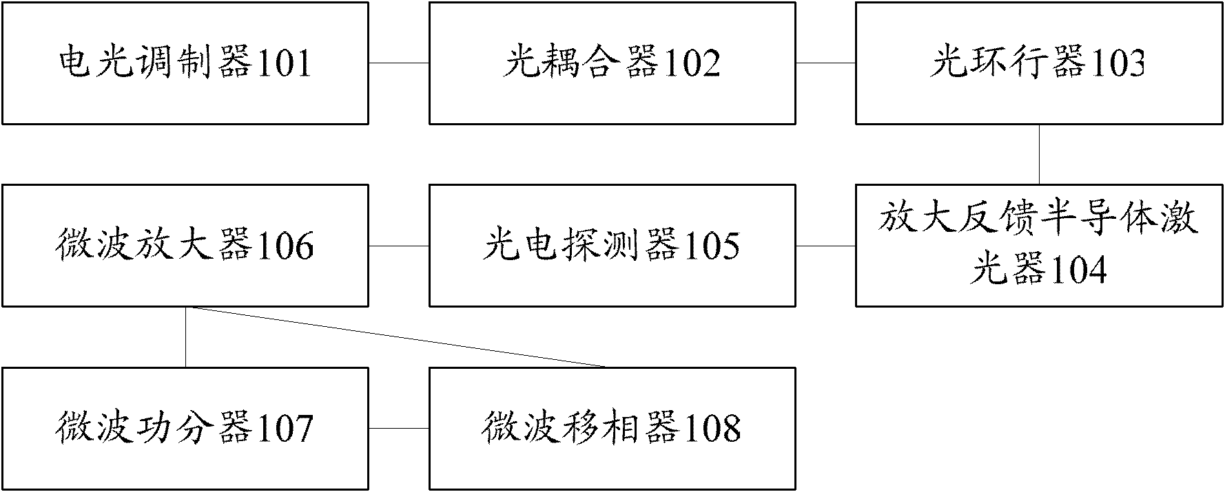
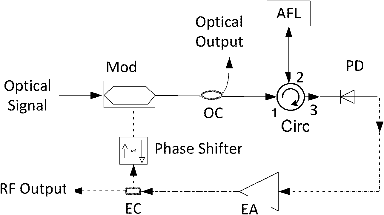
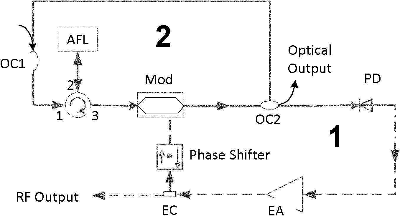
[0028] refer to figure 1 , shows a structural diagram of an optoelectronic oscillator based on photon filtering in the present invention, the oscillator includes: an electro-optic modulator (Mod) 101, an optical coupler (OC) 102, an optical circulator (Circ) 103, Amplified feedback semiconductor laser (AFL) 104, photodetector (PD) 105, microwave amplifier (EA) 106, microwave power divider (EC) 107 and microwave phase shifter (Phase Shifter) 108, wherein:

[0029] The electro-optic modulator 101 is used to modulate the incident laser light into an optical signal carrying the system clock of the optoelectronic oscillator, and the modulation frequency is the oscillation frequency of the optoelectronic oscillator;

[0030] An optical coupler 102, configured to couple the part of the optical signal modulated by the electro-optic modulator that meets the preset power value into the subsequent circulator;

[0031] The optical circulator 103 is used to receive the optical signal coup...


PUM


Abstract

The invention provides a photonic-filtering-based optoelectronic oscillator, which adopts an amplified feedback laser (AFL) as an optical domain filter instead of a conventional electric domain filter. A longitudinal intermode beat frequency microwave signal of the AFL serves as a drive source of a modulator for modulating laser injected into the AFL to form a self-feedback oscillatory system to further realize high-quality microwave and optical clock output functions.

Description

technical field [0001] The invention relates to the field of photoelectric hybrid technology, in particular to a photoelectric oscillator based on photon filtering. Background technique [0002] High-quality microwave signals have important applications in optical fiber, microwave, satellite communications, radar systems, precision instruments and meters, and high-precision measurement. Most of the high-quality microwave sources widely used at present rely on high-Q microwave energy storage devices (such as dielectric resonator oscillators) or surface acoustic wave devices (such as quartz crystal oscillators). These two types of devices perform well when working in the frequency band of several MHz to several GHz. However, when operating in the X-band or even higher frequencies, the quality of the microwave signals generated by these devices deteriorates sharply as the frequency increases due to the need for multiple frequency multiplications. The emergence of an Optoelect...

Claims


Application Information

Patent Timeline
IPC IPC(8): H01S5/06H01S5/065
Inventor 陆丹娄采云霍力
Owner TSINGHUA UNIV
Why Eureka
Try Eureka