Laser-guided electrospinning direct writing device

An electrospinning direct writing, laser-guided technology, used in textiles and papermaking, fiber processing, spinneret assemblies, etc. The operator's operation level has a great influence, and the nanofiber arrangement is difficult to control, etc., to achieve the effects of precise positioning and patterning preparation, prolonging the movement time and solvent evaporation time, and achieving orderly and controllable deposition and precise positioning.

Inactive Publication Date: 2011-08-24
XIAMEN UNIV
View PDF6 Cites 36 Cited by
  • Summary
  • Abstract
  • Description
  • Claims
  • Application Information

AI Technical Summary

Problems solved by technology

R.Dersch et al. ([4]R.Dersch, Taiqi Liu, A.K.Schaper, et al.Journal of Polymer Science Part A: Polymer Chemistry.Vol.41(4):545-553) adopted a three-dimensional metal groove structure as a collection Nanofibers can be deposited on both sides of the microgroove to form an orderly suspended structure, but as the deposition time of nanofibers increases, the movement of subsequent fibers will tend to be chaotic due to the influence of deposited fibers, and the arrangement of nanofibers is difficult to control , the distribution range and arrangement of nanofibers are limited by the pre-prepared collecting plate and cannot be changed arbitrarily
Sun et al. ([5]Sun D.H., Chang C., Li S., et al.Nano.Lett., 2006vol.6, pp.839-842.) and Chang et al. ([6]Chang C., Limkrailassiri K. , Lin L.W.Appl.Phys.Lett., 2008vol.93, pp.123111.) By shortening the distance from the nozzle to the collecting plate (0.5-3mm), the spinning jet is deposited on the collecting plate before entering the stage of disordered movement , the deposition of a single nanofiber is realized, and the electrospun nanofiber structure with different deposition trajectories can be prepared with the movement of the collecting plate, but the distance from the nozzle to the collecting plate is shortened, so that the deformation b...

Method used


Image

  • Laser-guided electrospinning direct writing device
  • Laser-guided electrospinning direct writing device

Examples


Embodiment Construction

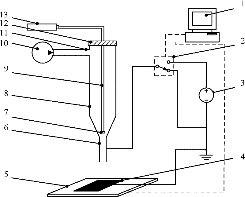
[0017] see figure 1 The embodiment of the present invention is provided with a computer 1, a high voltage relay 2, an electrostatic high voltage power supply 3, a hollow spray head 8, a collimating and focusing lens group 7, an optical fiber 9, a sealing end cap 12, a laser 13, a liquid supply pump 10, and a liquid supply pipe 11 , collecting plate 4 and motion platform 5.

[0018] The output terminal of the controller 1 is connected to the control terminal of the high-voltage relay 2, the normally open terminal of the high-voltage relay 3 is connected to the positive pole of the electrostatic high-voltage power supply 3, the normally-closed terminal of the high-voltage relay 2 is connected to the negative pole of the electrostatic high-voltage power supply 3 and the collecting plate 4 and then grounded, and the high-voltage relay 2 is common The end is connected with the conductor nozzle 6 located at the front end of the hollow nozzle, and the conductor nozzle 6 is coaxial wi...


PUM

PropertyMeasurementUnit
Lengthaaaaaaaaaa
The inside diameter ofaaaaaaaaaa

Abstract

The present invention provides a laser-guided electrospinning direct writing device capable of realizing long-time controllable preparation and precise positioning of single uniform micro/nanostructure. The device is provided with a controller, a high-voltage relay, an electrostatic high-voltage [power] source, a hollow nozzle, a collimating focusing lens set, optical fibers, a sealing adjusting part, a laser, a solution feed pump, a solution feed pipe, a collecting board and a motion platform, wherein the controller is connected with the high-voltage relay; ends of the high-voltage relay are respectively connected with the electrostatic high-voltage [power] source, the collecting board and a conductor nozzle arranged at the front end of the hollow nozzle; the sealing adjusting part is in a sealing connection with the rear end of the hollow nozzle; the optical fibers pass through the center of the sealing adjusting part and are fixedly connected with the sealing adjusting part; the collimating focusing lens set is arranged at the front end of the optical fibers; the rear end of the optical fibers comes out of the hollow nozzle and is connected with the laser; the solution feed pump is communicated with the hollow nozzle through the solution feed pipe; and the collecting board is fixed on the motion platform and faces the hollow nozzle. The laser constraints the disordered motion of spinning jet flow and guides the spinning jet flow to deposit at the laser spot of the collecting board.

Description

technical field [0001] The invention belongs to the technical field of electrospinning, and relates to an electrospinning direct writing device, in particular to a laser-guided electrospinning direct writing device. Background technique [0002] Electrospinning is the use of electrostatic force to stretch viscoelastic fluid, deform it to generate jets to realize the jetting of nanofibers; as an emerging micro-nano manufacturing technology, electrospinning technology is characterized by its low manufacturing cost, simple process, and wide source of raw materials. And many other advantages, has received extensive attention. Electrospun micro-nanostructures have a wide range of potential applications in flexible electronics, micro-nano devices, and high-sensitivity sensor devices. However, the electrospinning process is affected by many factors such as charge repulsion and fluid disturbance. The polymer jet has many unstable phenomena such as whipping and splitting. The flight...

Claims


Application Information

Patent Timeline
IPC IPC(8): D04H3/02D01D5/00D01D4/00D01D1/06D01D13/00
Inventor 郑高峰王磊
Owner XIAMEN UNIV
Why Eureka
Try Eureka