Biconical rotary vacuum drying system

A vacuum drying and vacuum pump technology, which is applied in the direction of drying solid materials, non-progressive dryers, and drying solid materials without heating, can solve problems such as inappropriate drying of lithium iron phosphate materials, affecting product purity, and affecting dryness. To achieve the effect of convenient replacement, guaranteed purity and energy saving

Active Publication Date: 2011-08-31
JIANGSU XIANFENG DRYING ENG
7 Cites 6 Cited by

AI-Extracted Technical Summary

Problems solved by technology

Generally speaking, the finished products unloaded from the double-cone rotary vacuum dryer need to be transferred to another special equipment for cooling. The hot materials are easy to absorb moisture during the transportation process, which will affect the dryness and be easily polluted, which will affect the purity of the product.
[0005] During...

Method used

[0032] The condenser 3 is stacked above the gas-liquid separator 4 by a support 20. The condenser 3 is a spiral plate condenser, which is available in the market. The condenser 3 has an air inlet 3-1, an air outlet 3-2, a cooling medium inlet 3-3 and a cooling medium outlet. The spiral plate condenser is made of two sheets, forming two uniform spiral channels. The two heat transfer media can flow in full countercurrent, which greatly enhances the heat exchange effect. Can ac...

Abstract

The invention relates to a biconical rotary vacuum drying system, which comprises a biconical rotary vacuum drying main machine, a condenser, a gas-liquid separator, a vacuum pump, an oil pump, a hot oil tank, a vacuumizing pipe, an oil supply pipe and an oil return pipe, wherein the vacuumizing pipe extends into a cylinder body of the biconical rotary vacuum drying main machine from the inner cavity of a driving half shaft and the pipe hole of a driving shaft base; the oil supply pipe extends into an oil inlet cavity from the inner cavity of a driven half shaft and a pipe hole on a baffle; and two built-in oil supply branch pipes which are arranged horizontally on front and back sides are arranged on the middle part of a clamp sleeve of the cylinder body and are communicated with an oil inlet cavity of a driven shaft base. By the biconical rotary vacuum drying system, heat conducting oil can be distributed to integral clamp sleeve space uniformly to ensure the uniformity of clamp sleeve heating, the problem that biconical rotary vacuum drying is 'semi-hot and semi-cold' for a long term is solved, the quality of products and the work efficiency are improved, and energy is saved. In the biconical rotary vacuum drying system, solvents are recovered by a gas condenser and a liquid separator.

Application Domain

Technology Topic

SolventBicone +7

Image

  • Biconical rotary vacuum drying system
  • Biconical rotary vacuum drying system
  • Biconical rotary vacuum drying system

Examples

  • Experimental program(2)

Example Embodiment

[0024] Example 1
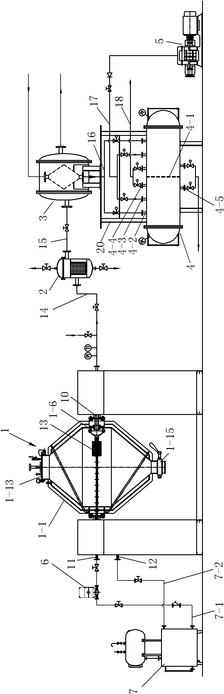
[0025] See Figure 1 to Figure 4 , this embodiment includes a double-cone rotary vacuum drying host 1, a bag filter 2, a condenser 3, a gas-liquid separator 4, a vacuum pump 5, an oil pump 6, a hot oil tank 7, a vacuum pipe 10, an oil supply pipe 11 and an oil return pipe 12.
[0026] The hot oil tank 7 is provided with a hot oil tank oil delivery pipe 7-1 and a hot oil tank oil return pipe 7-2, the hot oil tank oil delivery pipe 7-1 is connected with the oil pump 6, the oil pump 6 is connected with the oil supply pipe 11, and the hot oil tank Oil return pipe 7-2 is connected with oil return pipe 12. The hot oil tank oil delivery pipe 7-1 and the hot oil tank oil return pipe 7-2 are all provided with corresponding valves.
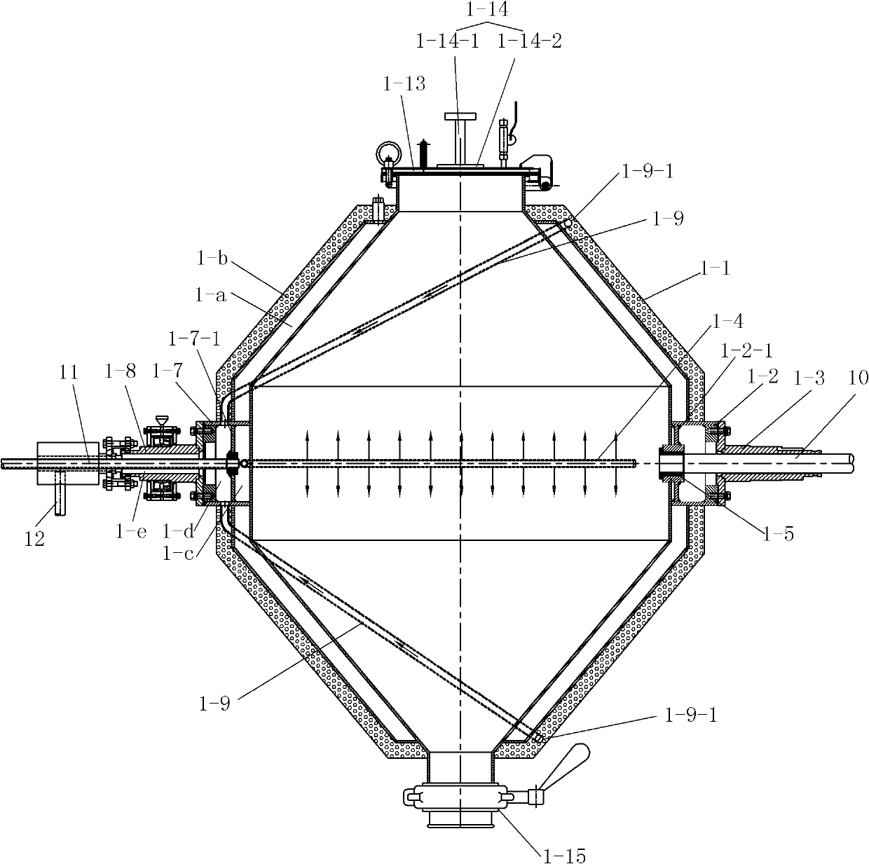
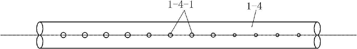
[0027] The jacketed cylinder body 1-1 of the double-cone rotary vacuum drying main engine 1 is provided with a feed pipe, a discharge pipe, a driving shaft seat installation hole and a driven shaft seat installation hole, and a feed pipe is provided with a feed pipe. Cover 1-13, discharge device 1-15 is provided on the discharge pipe. The mounting hole of the driving shaft seat and the mounting hole of the driven shaft seat are respectively fixed with the driving shaft seat 1-2 and the driven shaft seat 1-7. The main shaft of the double-cone rotary vacuum drying host 1 is composed of a hollow driving half-shaft 1-3 and a hollow driven half-shaft 1-8, and the driving half-shaft 1-3 and the driven half-shaft 1-8 are respectively fixed on the driving shaft seat 1- 2 and in the driven shaft seat 1-7. The drive shaft seat 1-2 is provided with a support plate 1-2-1, and the support plate 1-2-1 is provided with a tube hole, and the vacuum tube 10 passes through the inner cavity of the drive half shaft 1-3 and the support plate 1-2 The tube hole on -1 extends into the cylinder body 1-1, and a first sealing ring 1-5 is arranged between the vacuum tube 10 and the tube hole wall on the support plate 1-2-1. The inner wall of the cylinder 1-1 of the double-cone rotary vacuum drying host 1 is fixed with a cover seal 1-6 covering the driving shaft seat mounting hole therein, and the vacuum pumping tube 10 is inserted into the cover seal 1-6. The cover seal 1-6 includes a cover seal seat 1-6-1 and a cover cover 1-6-2, and the cover seal seat 1-6-1 and the cover cover 1-6-2 are connected by bolts 1-6 -3 connection, the joint needs to meet the sealing requirements, the cover seal seat 1-6-1 is fixed on the inner wall of the cylinder, the cover cover 1-6-2 has a stretching tube 1-6-2-1, The filter element 13 is connected to the stretching tube 1-6-2-1.
[0028] The inner cavity of the driven shaft seat 1-7 is divided into an oil inlet chamber 1-c and an oil return chamber 1-d by a partition 1-7-1, and a tube hole is arranged on the partition 1-7-1, so The oil supply pipe 11 extends into the oil inlet chamber 1-c through the inner cavity of the driven half shaft 1-8, the pipe hole on the partition plate 1-7-1 and the oil return chamber 1-d. A second sealing ring 1-10 is provided between the oil supply pipe 11 and the pipe hole wall on the partition plate 1-7-1 of the driven shaft seat 1-7.
[0029]The middle part of the jacket 1-a of the cylinder body 1-1 has two built-in oil supply branch pipes 1-4 located on the front and rear sides and placed horizontally. One end of the two built-in oil supply branch pipes 1-4 is connected to the driven shaft seat 1- The oil inlet chamber 1-c in the 7 communicates, and the other ends of the two built-in oil supply branch pipes 1-4 are as close as possible. The pipe wall of the built-in oil supply branch pipe 1-4 is provided with two rows of oil holes 1-4-1 for spraying oil upwards and downwards respectively.
[0030] The upper and lower ends of the jacket 1-a of the cylinder 1-1 are respectively provided with oil return holes 1-9-1 at the parts away from the oil inlet cavity 1-c of the driven shaft seat. The insulation layer 1-b is provided with built-in oil return branch pipes 1-9 at the upper and lower parts respectively, and one end of the built-in oil return branch pipe 1-9 is connected to the corresponding oil return hole 1-9-1 on the jacket 1-a, The other end is inserted into the oil return cavity 1-d of the driven shaft seat 1-7. The gap between the oil supply pipe 11 and the inner wall of the driven half shaft 1-8 is the oil return channel 1-e, and one end of the oil return channel 1-e communicates with the oil return chamber 1-d in the driven shaft seat 1-7 , the oil return pipe 12 is connected to the other end of the oil return channel 1-e.
[0031] An impact device 1-14 is provided on the feed cover 1-13 of the drying host cylinder body 1-1, and the impact device 1-14 includes an impact rod 1-14-1 and a Impact block 1-14-2. During the tumbling process of the cylinder, the impact block 1-14-2 moves on the impact rod 1-14-1 due to gravity, and impacts the feed cover 1-13 to prevent sticking on the inner wall of the feed cover 1-13. wall.
[0032] The condenser 3 is stacked above the gas-liquid separator 4 through a bracket 20 . The condenser 3 is a spiral plate condenser, which is available in the market. The condenser 3 has an air inlet 3-1, an air outlet 3-2, a cooling medium inlet 3-3 and a cooling medium outlet. The spiral plate condenser is made of two sheets, forming two uniform spiral channels. The two heat transfer media can flow in full countercurrent, which greatly enhances the heat exchange effect. Can achieve the ideal heat exchange effect. Secondly, the connecting pipe on the casing adopts a tangential structure, and the local resistance is small. Since the curvature of the spiral channel is uniform, the liquid flows in the equipment without a large turn, and the total resistance is small, so the design flow rate can be increased to make it have a higher heat transfer capacity.
[0033] The tank body of the gas-liquid separator 4 is provided with a middle partition 4-1, and the tank inner cavity is divided into two chambers, and the corresponding two chambers on the tank body are respectively provided with an air inlet 4-2, an exhaust port 4-3, Fresh air inlet 4-4 and drain port 4-5 are provided with corresponding pipes connected with air inlet 4-2, exhaust port 4-3, fresh air inlet 4-4 and drain port 4-5. valve. The above two chambers collect the solvent in turn and discharge the material in turn.
[0034] The double-cone rotary vacuum drying host 1 is connected to the air inlet of the bag filter 2 through the suction pipe 10 and the first connecting pipe 14, and the exhaust port of the bag filter 2 is connected to the air inlet of the bag filter 2 through the second connecting pipe 15. The air inlet of the condenser 3 is connected, the exhaust port of the condenser 3 is connected with the two air inlets 4-2 of the gas-liquid separator 4 through the third connecting pipe 16, and the two air inlets 4-2 of the gas-liquid separator 4 The exhaust port 4 - 3 is connected with the vacuum pump 5 through the fourth connecting pipe 17 . Corresponding valves are provided on the oil supply pipe 11 , the first connecting pipe 14 , the second connecting pipe 15 and the fourth connecting pipe 17 . The solvent is collected through two discharge ports 4-5 of the gas-liquid separator 4.

Example Embodiment

[0035] Example 2
[0036] On the basis of Embodiment 1, the present embodiment is also provided with a transfer oil tank 8 and a cold oil tank 9. The transfer oil tank 8 is an insulated oil tank. The transfer oil tank 8 is provided with a transfer oil tank oil delivery pipe 8-1 and a transfer oil tank return pipe 8-2. 9 is provided with a cold oil tank oil delivery pipe 9-1 and a cold oil tank return pipe 9-2, the transfer oil tank oil delivery pipe 8-1 is connected with the hot oil tank 7, the cold oil tank oil delivery pipe 9-1 is connected with the hot oil tank oil delivery pipe 7-1, and the transfer oil tank return oil pipe 8-2 and the oil return pipe 9-2 of the cold oil tank are connected with the oil return pipe 12. Each has a corresponding valve.
[0037] When working, the oil pump 6 is turned on, the valve K1 on the oil delivery pipe 8-1 of the transfer oil tank is normally open, the valve K2 on the return oil pipe 7-2 of the hot oil tank, the valve K 3 on the oil delivery pipe 7-1 of the hot oil tank, and the oil supply pipe 11 The valve K 4 of the valve is opened, and the heat transfer oil circulates between the hot oil tank 7 and the jacket 1-a of the double-cone rotary vacuum drying host 1, and the heating system works normally. When the material is cooled, the oil pump 6 is turned on at this time, the valves K and 5 on the oil delivery pipe 9-1 of the cold oil tank, and the valve K6 on the oil return pipe 8-2 of the transfer oil tank are turned on. At this time, the hot oil in the jacket enters the transfer oil tank first. A certain amount, the valve K6 is closed, the valve K7 on the oil return pipe 9-2 of the cold oil tank is opened, and the cooling oil circulates between the cold oil tank 9 and the jacket 1-a of the double-cone rotary vacuum drying host 1 to cool the material. When drying again, the oil in the transfer oil tank enters the hot oil tank 7 for utilization.
[0038] In this embodiment, waste heat is utilized by transferring the oil tank, saving energy.

PUM

no PUM

Description & Claims & Application Information

We can also present the details of the Description, Claims and Application information to help users get a comprehensive understanding of the technical details of the patent, such as background art, summary of invention, brief description of drawings, description of embodiments, and other original content. On the other hand, users can also determine the specific scope of protection of the technology through the list of claims; as well as understand the changes in the life cycle of the technology with the presentation of the patent timeline. Login to view more.

Similar technology patents

Classification and recommendation of technical efficacy words

  • Guaranteed uniformity
  • Uniform fineness

Visual soil freeze-thawing process test apparatus

Owner:NORTHWEST INST OF ECO-ENVIRONMENT & RESOURCES CAS

Preparation method of resin coated color quartz sand

ActiveCN104478258AFully coloredUniform finenessWork in processPolyresin
Owner:苏州大乘环保新材有限公司

Conductive fiber composite spinning component

PendingCN108517575AImprove composite effectUniform finenessFilament/thread formingEngineeringFiber
Owner:JIANGSU ZJA NEW MATERIAL
Why Eureka
Try Eureka