
Optical fiber wavelength division multiplexing device and annular cavity optical fiber laser containing same

A technology of wavelength division multiplexing devices and fiber lasers, which is applied to the coupling of lasers, optical waveguides, and laser components, etc., can solve the problems of increasing coupling difficulty and stability, increasing component volume and weight, and only output power. Effects of increased coupling power and efficiency, enhanced interaction, and increased peak power

Inactive Publication Date: 2011-08-31
PEKING UNIV
View PDF3 Cites 3 Cited by
  • Summary
  • Abstract
  • Description
  • Claims
  • Application Information

AI Technical Summary

Problems solved by technology

However, the pumping power is space coupling, the pumping laser power is 1.4W, and the output power can reach up to 500mW; the coupling between the optical fiber and the collimator lens is also space coupling, which increases the difficulty and stability of coupling, and Component size and weight
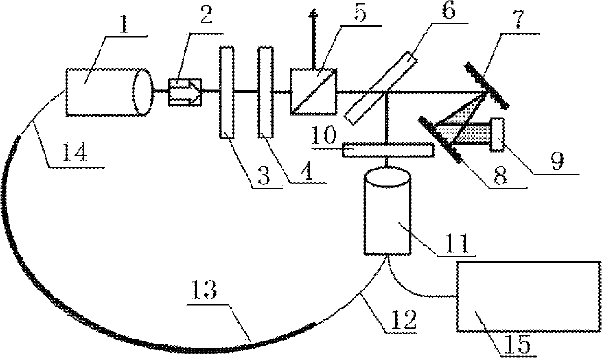
[0006] J.L. Morse, J.W. Sickler, J. Chen, F.X. The ring cavity fiber laser proposed in the article "Highrepetition rate, high average power, femtosecond erbium fiber ring laser" published by E.P.Ippen at the Conference on Laser and Electro-optics (CLEO) in 2009, removes the fiber through spatial coupling The wavelength division multiplexing collimator can increase the repetition frequency of the fiber laser oscillator to 301MHz, but the spatial coupling will bring loss and instability. The pumping power of the laser is 1.2W, and the output power is only 61mW

Method used


Image

  • Optical fiber wavelength division multiplexing device and annular cavity optical fiber laser containing same
  • Optical fiber wavelength division multiplexing device and annular cavity optical fiber laser containing same
  • Optical fiber wavelength division multiplexing device and annular cavity optical fiber laser containing same

Examples


Embodiment Construction

[0030] The optical fiber wavelength division multiplexing device proposed by the present invention and the ring cavity fiber laser including the device are described in detail below with reference to the drawings and embodiments.

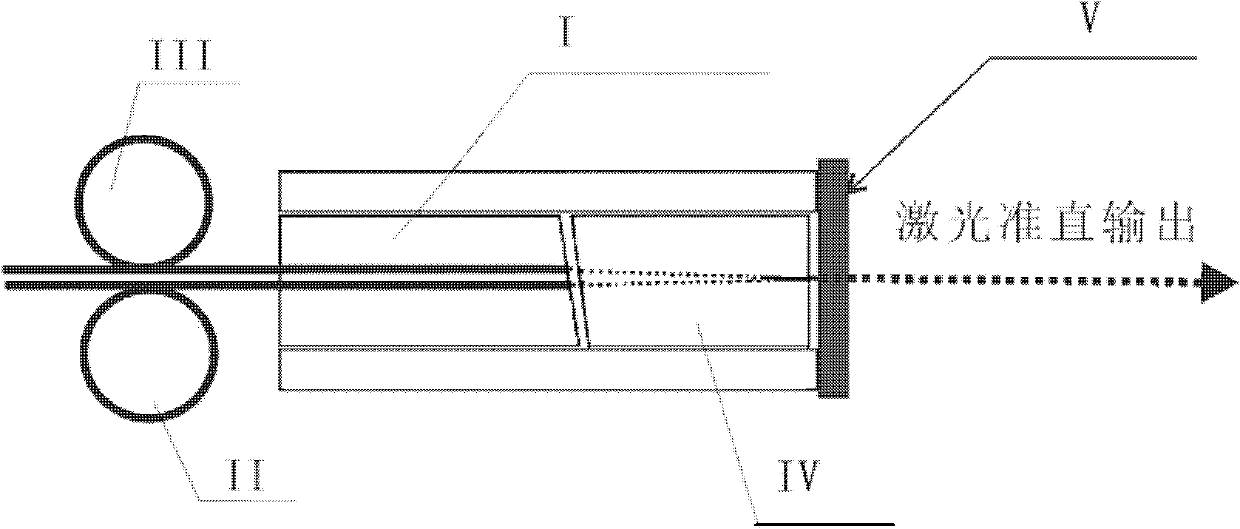
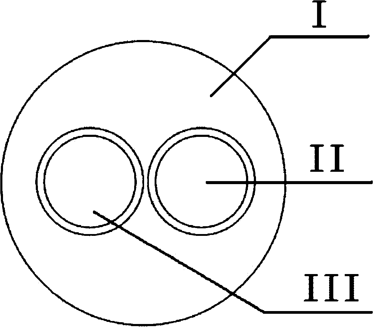
[0031] Such as figure 1 As shown, an integrated optical fiber wavelength division multiplexing (Wavelength Division Multiplexing, WDM) device according to an embodiment of the present invention includes: a double-tailed fiber optic collimation lens, and a WDM fiber optic collimation lens is fixed on one end surface of the double-tailed fiber optic collimation lens. Diaphragm V, or coated with a film that can realize WDM. This device is a device that integrates WDM and optical fiber collimation functions. This device can ensure that the incident light is coupled into the gain fiber to the maximum extent, and the laser running in the optical fiber can be transmitted through the device to the maximum extent and collimated output.

[0032] Wherein, the...


PUM

PropertyMeasurementUnit
Diameteraaaaaaaaaa

Abstract

The invention discloses an optical fiber wavelength division multiplexing device and an annular cavity optical fiber laser containing same. The optical fiber wavelength division multiplexing device comprises a double-tail fiber collimating lens, wherein a fiber wavelength division multiplexing membrane is fixed on one end face of the double-tail fiber collimating lens or a membrane which can be used for realizing the wavelength division multiplexing is plated on one end face of the double-tail fiber collimating lens. By using the optical fiber wavelength division multiplexing device and the annular cavity optical fiber laser containing the same provided by the invention, the loss and instability caused by the space coupling can be avoided while the optical fiber length of the optical fiber laser is reduced and the repetition rate is increased, thereby increasing the resolution ratio when used as the frequency comb of a light source.

Description

technical field [0001] The invention relates to the technical field of mode-locked fiber laser and frequency comb measurement, in particular to an optical fiber wavelength division multiplexing device and a ring cavity fiber laser including the device. Background technique [0002] Optical frequency combs are used to achieve extremely precise measurements of optical frequencies, which are generated by mode-locked lasers, which are ultrashort pulse lasers. The carrier wave of the ultrashort optical pulse is composed of light of a single frequency, which will appear as a vertical line on the spectrum at this frequency, indicating that only light waves of this frequency exist. Here, two characteristics of the light pulses emitted by the mode-locked laser are key to developing an optical frequency comb. The first feature is the pulse phase: a small displacement of the envelope relative to the carrier, resulting in a slight change in the pulse, the peak of the pulse envelope can...

Claims


Application Information

Patent Timeline
IPC IPC(8): G02B6/293G02B6/32G02B1/11H01S3/067H01S3/00
Inventor 王爱民李鹏宗伟健张志刚
Owner PEKING UNIV
Learn More