Supercharge Your Innovation With Domain-Expert AI Agents!

Light pulse repetition rate expander and laser application system

A technology of repetition frequency and optical pulse, applied in the fields of instruments, optics, nonlinear optics, etc., can solve the problems of low repetition frequency and output power of pulsed lasers, and achieve the goal of overcoming bad nonlinear effects, simple structure, and improving output power level. Effect

Active Publication Date: 2013-03-20
阮双琛 +2
View PDF0 Cites 0 Cited by
  • Summary
  • Abstract
  • Description
  • Claims
  • Application Information

AI Technical Summary

Problems solved by technology

[0004] The purpose of the embodiments of the present invention is to provide an optical pulse repetition frequency expander, which aims to solve the problem of low repetition frequency and output power of existing pulsed lasers

Method used


Image

  • Light pulse repetition rate expander and laser application system
  • Light pulse repetition rate expander and laser application system

Examples


Embodiment 1

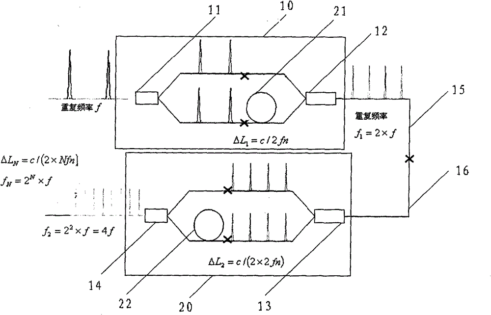
[0016] Such as figure 1 As shown, the optical pulse repetition frequency expander provided by the embodiment of the present invention is a quadrupled optical pulse repetition frequency expander based on a 1×2 coupler pair, which includes a first coupler 11, a second coupler 12, a third The coupling ratio of the coupler 13 and the fourth coupler 14 is 50:50. The two output ends of the first coupler 11 and the second coupler 12 are respectively fused to form two connection arms, and a section of length ΔL is connected to one of the connection arms. 1 The first optical fiber 21 of =c / 2fn makes this connecting arm longer than the other connecting arm ΔL 1 =c / 2fn, these two couplers form the first coupler pair 10 (i.e. the first-stage frequency multiplier 10), and realize the first-stage frequency multiplication, namely f 1 =2×f, this is the double frequency.

[0017] Similarly, the third coupler 13 and the fourth coupler 14 form a second coupler pair 20 (i.e. a second-stage fre...

Embodiment 2

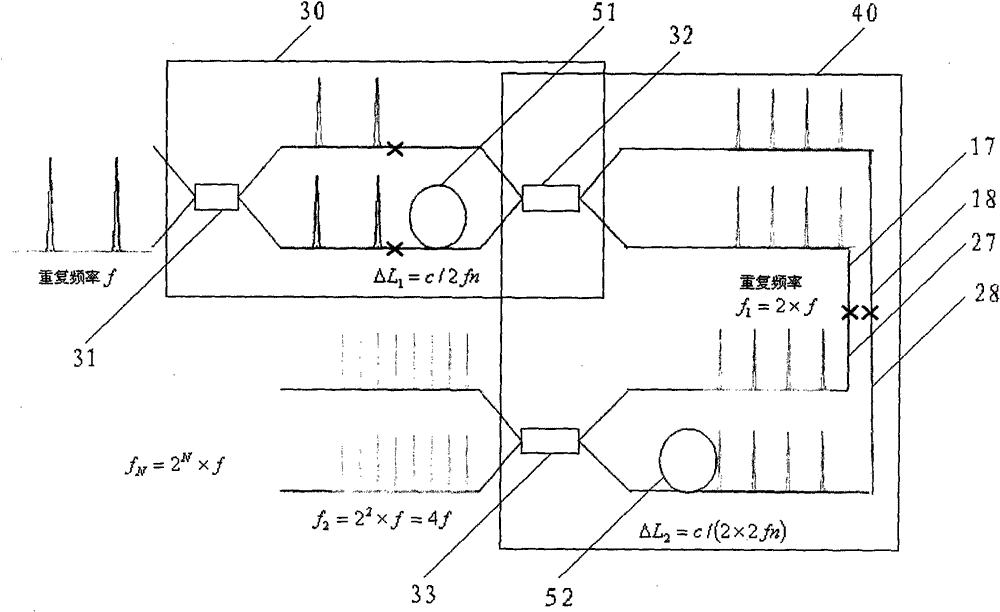
[0023] Such as figure 2 As shown, the optical pulse repetition frequency expander provided by the embodiment of the present invention is a quadrupled optical pulse repetition frequency expander based on a 2×2 coupler pair, which includes a first coupler 31, a second coupler 32 and a third Coupler 33, each coupler is a 2×2 type coupler, and the coupling ratio of each coupler is 50:50, wherein the first coupler 31 and the second coupler 32 constitute the first coupler pair 30 (i.e. the first Primary frequency multiplier 30). The structure of the first coupler pair 30 is similar to that of the first coupler pair 10 in the first embodiment, except that in this embodiment, each coupler pair has two connecting arms at the input end and the output end.

[0024] In the embodiment of the present invention, the two connecting arms 17, 18 at the output end of the first coupler pair 30 can be respectively welded with the two connecting arms 27, 28 at the input end of the third coupler 3...


PUM


Abstract

The invention is fit for photoelectric field and provides a light pulse repetition rate expander and a laser application system. The light pulse repetition rate expander is a cascaded optical fiber coupler which is formed by connecting a plurality of coupler pairs in sequence, wherein each coupler pair comprises an input end, an output end and two connecting arms; one connecting arm is delta LN longer than the other connecting arm, wherein the delta LN = c / (2*Nfn), N is the cascade number of the cascaded optical fiber coupler, and n is the fiber core refractive index of an optical fiber. The embodiment of the invention designs a full optical fiber light pulse repetition rate expander by introducing an optical path difference into one connecting arm of the cascaded optical fiber coupler. The expander has simple structure and low cost. The light pulse repetition rate expander can be used for expanding the repetition rate of the pulse laser frequently used at present, especially for performing the multistage frequency-doubling expansion of repetition rate on lasers with repetition rates of MHZ (megahertz) picosecond pulse and KHZ (kilohertz) nanosecond pulse, so as to increase the output power level of the present pulse optical fiber laser.

Description

technical field [0001] The invention belongs to the field of optoelectronics, in particular to an optical pulse repetition frequency expander and a laser application system. Background technique [0002] High-power picosecond or nanosecond pulsed fiber lasers generally adopt a master oscillation power amplification (MOPA) structure, that is, a fiber amplifier is used to amplify the power of the picosecond or nanosecond seed pulse laser. After amplification, high peak power and large single pulse energy will be generated, which will cause a strong nonlinear effect. At the same time, excessive pulse energy and peak power after amplification will cause laser damage to the output end face of the fiber and burn the end face. In this way, the strong nonlinear effect and the damage effect of the laser end face limit the power (average power) amplification level of the amplifier. [0003] However, the repetition frequency of passive mode-locked picosecond laser pulses of general al...

Claims


Application Information

Patent Timeline
Patent Type & Authority Patents(China)
IPC IPC(8): G02F1/377
Inventor 阮双琛郭春雨陈祖聪潘尔明闫培光
Owner 阮双琛
Features
  • R&D
  • Intellectual Property
  • Life Sciences
  • Materials
  • Tech Scout
  • Unparalleled Data Quality
  • Higher Quality Content
  • 60% Fewer Hallucinations
Learn More