Power storage device separator
A technology for power storage devices and diaphragms, which is applied in the direction of hybrid capacitor separators, circuits, capacitors, etc., can solve the problems of hindering ion movement, deterioration of strength and durability, and inability to maintain product characteristics, achieving good durability and good heat resistance. Excellent effect of chemical resistance, solvent resistance and ion permeability
- Summary
- Abstract
- Description
- Claims
- Application Information
AI Technical Summary
Problems solved by technology
Method used
Image
Examples
Embodiment 1
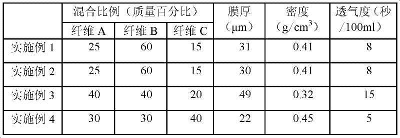
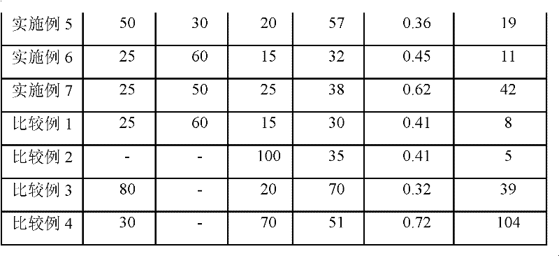
[0090] Fiber A made of polyethylene terephthalate fibers with a fiber diameter of 2.5 μm, a fiber length of 6 mm, and a crystallinity of 55% was fibrillated to a fiber diameter of 0.2 μm and a fiber length of 0.6 mm. The fiber B of fiber B, fibrillation into fiber diameter 0.5 μm, the fiber C that the fiber length 1mm is made of solvent spinning cellulose are dropped into ion-exchanged water according to the mass ratio of 25:60:15 respectively and by the concentration of 0.05% by mass, Disperse in a beater for 30 minutes to obtain a papermaking material composed of a fiber dispersion.
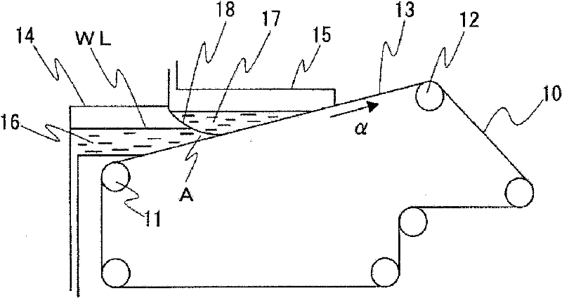
[0091] The above-mentioned papermaking materials were made into wet paper sheets (··········) using a standard type hand papermaking device specified in JIS P8222. Then, after taking out the obtained wet paper sheet from the handsheet machine, it was dried at 130 degreeC with the Yankee dryer, and the separator of this invention was obtained. As physical properties of the obtained separator, t...
Embodiment 2
[0093] Fiber A composed of polyethylene terephthalate fibers with a fiber diameter of 2.5 μm, a fiber length of 6 mm, and a crystallinity of 73% was fibrillated to a fiber diameter of 0.2 μm and a fiber length of 0.6 mm. The fiber B of fiber B, fibrillation into fiber diameter 0.5 μm, the fiber C that the fiber length 1mm is made of solvent spinning cellulose are dropped into ion-exchanged water according to the mass ratio of 25:60:15 respectively and by the concentration of 0.05% by mass, Disperse in a beater for 30 minutes to obtain a papermaking material composed of a fiber dispersion.
[0094] The above-mentioned papermaking materials were sheeted into wet paper sheets using a standard type handsheeting apparatus specified in JIS P8222. Then, after taking out the obtained wet paper sheet from the handsheet machine, it was dried at 130 degreeC with the Yankee dryer, and the separator of this invention was obtained. As physical properties of the obtained separator, the film...
Embodiment 3
[0096] Fiber A made of polyethylene terephthalate fibers with a fiber diameter of 3.2 μm, a fiber length of 6 mm, and a crystallinity of 55% was fibrillated to a fiber diameter of 0.2 μm and a fiber length of 0.6 mm. The fiber B of fiber B, fibrillation into fiber diameter 0.5 μm, the fiber C that fiber length 1mm is made of solvent spinning cellulose are dropped into ion-exchanged water according to the mass ratio of 40:40:20 respectively and by the concentration of 0.05% by mass, Disperse in a beater for 30 minutes to obtain a papermaking material composed of a fiber dispersion. Then, the separator of the present invention was obtained in the same manner as in Example 1. As physical properties of the obtained separator, the film thickness of the separator was 49 μm, and the density was 0.32 g / cm 3 , the air permeability is 15 seconds / 100ml.
PUM
| Property | Measurement | Unit |
|---|---|---|
| diameter | aaaaa | aaaaa |
| length | aaaaa | aaaaa |
| thickness | aaaaa | aaaaa |
Abstract
Description
Claims
Application Information
 - R&D
- Intellectual Property
- Life Sciences
- Materials
- Tech Scout
- Unparalleled Data Quality
- Higher Quality Content
- 60% Fewer Hallucinations
Browse by: Latest US Patents, China's latest patents, Technical Efficacy Thesaurus, Application Domain, Technology Topic, Popular Technical Reports.
© 2025 PatSnap. All rights reserved.Legal|Privacy policy|Modern Slavery Act Transparency Statement|Sitemap|About US| Contact US: help@patsnap.com


