M-BUS (Meter-Bus) driving circuit

An M-BUS, bus-driven technology, applied in the field of electronics, can solve the problems of communication failure, decrease in the number of terminal devices, communication cannot be carried out normally, etc., to ensure safety and stability, avoid the influence of interference signals, and improve communication reliability. Effect

Active Publication Date: 2011-09-14
AMPHENOL AORORA TECH (HUIZHOU) CO LTD
View PDF3 Cites 9 Cited by
  • Summary
  • Abstract
  • Description
  • Claims
  • Application Information

AI Technical Summary

Problems solved by technology

When each node terminal is in data communication, all node devices are switched from sleep state to working state, and the power consumption of terminal node devices is doubled (generally increased from 5uA to about 300uA), and the completion of all terminal node The total communication time is relatively long. During the communication process, the bus driver generates heat and the bus voltage drop increases. When the load exceeds a certain level, the communication cannot be carried out normally.
A lot of practical use has proved that the existing M-BUS bus driver circuit can carry terminal node devices (5uA in sleep mode, 300uA when awakened) and can only carry about 150 terminal node devices, and more than 180-200 devices are easy to appear Communication failure phenomenon
[0005] (2) Since the amplitude of the communication downlink pulse is relatively small (10V-12V), when external interference signals are superimposed on the bus, it is easy to cause data errors, and the reliability of the communication must be guaranteed by reducing the baud rate
[0008] (3) Since each node terminal relies on the conversion of the current loop to transmit data upstream, external interference signals are superimposed on the current loop, which may easily lead to signal errors. Properly increasing the current loop current of the terminal node equipment is good for improving its anti-interference ability However, increasing the current loop current of the terminal equipment will lead to an increase in its power consumption, and the increase in the power consumption of the terminal equipment will inevitably lead to a reduction in the number of terminal equipment carried by the M-BUS

Method used


Image

  • M-BUS (Meter-Bus) driving circuit
  • M-BUS (Meter-Bus) driving circuit
  • M-BUS (Meter-Bus) driving circuit

Examples


Embodiment Construction

[0018] In order to facilitate the understanding of those skilled in the art, the present invention will be further described in detail below with reference to the drawings and embodiments.

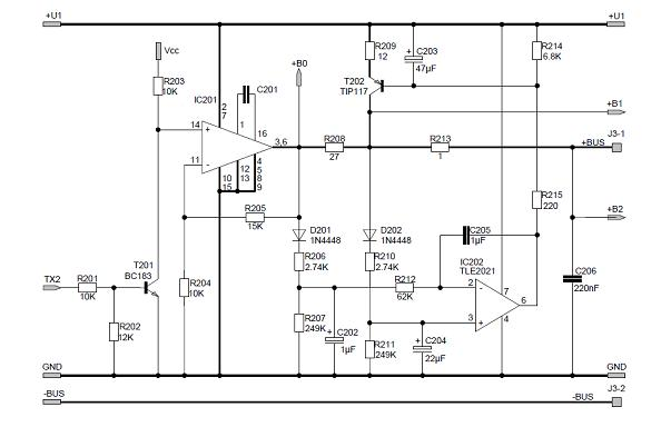
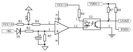
[0019] The characteristics of the M-BUS bus driving circuit of the present invention mainly lie in its signal sending circuit and power supply circuit.

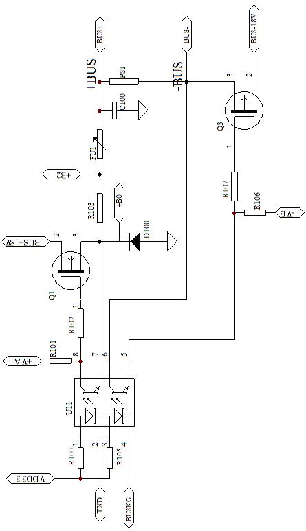
[0020] Such as figure 2 As shown, the signal sending circuit of the M-BUS bus driving circuit disclosed in this embodiment includes an optocoupler U11, a first MOSFET Q1 and a second MOSFET Q2, and the optocoupler chip contains two optocoupler devices.

[0021] Among them, the gate of the first MOSFET Q1 is connected to the collector of the first optocoupler through the resistor R102, the drain is connected to the current limiting resistor R103, the resettable fuse FU1 and the filter capacitor C100 in turn, the other end of the filter capacitor is grounded, and the resettable fuse FU1 is connected to the other end. One end is used as th...


PUM


Abstract

The invention relates to an M-BUS (Meter-Bus) driving circuit. A signal transmission circuit of the circuit comprises optocouplers, a first MOSFET (Metal-Oxide -Semiconductor Field Effect Transistor) and a second MOSFET, wherein a grid of the first MOSFET is connected with a collector of the first optocoupler, a drain of the first MOSFET is connected with an anode of a bus power supply, and a source of the first MOSFET is connected with an emitter of the first optocoupler and used as a positive output end of the signal transmission circuit; and a grid of the second MOSFET is connected with an emitter of the second optocoupler, a drain of the second MOSFET is connected with a cathode of the bus power supply, and a source of the second MOSFET is connected with a collector of the second optocoupler and used as a negative output end of the signal transmission circuit. In the invention, the signal transmission circuit and the power supply circuit are constructed by using the MOSFETs to provide power supply to a node on the M-BUS; and because the internal resistance of the MOSFETs is small and the load capacity is strong, an increasing number of terminal equipments can be hung on the M-BUS bus; meanwhile, the amplitude value of an output signal is increased, the influence from an interference signal is effectively avoided and the communication reliability is improved by using the circuit.

Description

technical field [0001] The invention relates to the field of electronic technology, in particular to an M-BUS bus drive circuit. Background technique [0002] M-BUS (Meter-BUS, EN1434-3) is an international standard for consumer instruments. Its topology is a bus structure. It is connected by an ordinary two-core cable. The two-core cable simultaneously completes the functions of power supply and data communication. It is widely used. It is used in the fields of centralized reading of three meters, intelligent home control network, fire alarm and linkage network, residential intelligent control network, central air-conditioning control system, etc. [0003] The M-BUS bus drive circuit structure mainly includes seven parts, namely: power supply module, sending module, receiving module, M-BUS interface, overload detection circuit, relay circuit, and host communication interface. Such as figure 1 , is the existing M-BUS bus drive circuit diagram, which has the following defic...

Claims


Application Information

Patent Timeline
Patent Type & Authority Applications(China)
IPC IPC(8): H04L25/02
Inventor 罗学武
Owner AMPHENOL AORORA TECH (HUIZHOU) CO LTD
Why Eureka
Try Eureka