Device and method for slag afterheat self-decomposition

A technology of waste heat self-decomposition and steel slag, which is applied in the field of converter steel slag treatment and steel slag waste heat self-decomposition treatment device under pressure, which can solve the problems of poor gelling performance, high equipment failure rate, equipment wear, etc. Good chemical effect and short processing cycle

Active Publication Date: 2011-09-21
CENT RES INST OF BUILDING & CONSTR CO LTD MCC GRP +2
View PDF3 Cites 3 Cited by
  • Summary
  • Abstract
  • Description
  • Claims
  • Application Information

AI Technical Summary

Problems solved by technology

Problems to be solved in this process: the low treatment rate of steel slag is generally below 50%, and there is still a large amount of dry slag discharged; the power consumption of system equipment is high, the failure rate of equipment is high, and the investment is large; steel slag is not easy to be crushed and granulated. The equipment is severely worn, and the steel balls inside are often replaced
The granulation wheel process is to transport the liquid steel slag to the processing workshop, use a crane to slowly lift the slag tank, pour it into the high-speed rotating granulation wheel, break and granulate the steel slag, spray water to cool it, and then fall into the pool. After being treated by granulation wheel water quenching method, the particle size is small, the steel slag crystallizes densely, it is difficult to grind finely, and its gelling performance becomes poor, which affects the application of steel slag in the building material industry

Method used


Image

  • Device and method for slag afterheat self-decomposition
  • Device and method for slag afterheat self-decomposition
  • Device and method for slag afterheat self-decomposition

Examples


Embodiment Construction

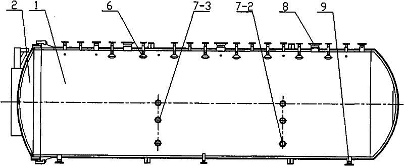
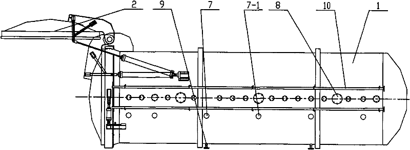
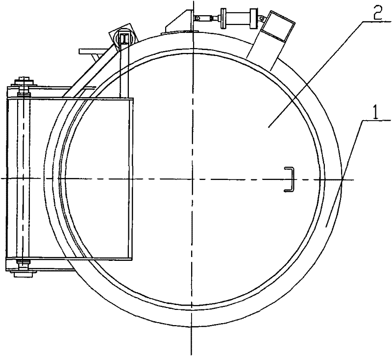
[0022] like figure 1 , 2 , 3 is a schematic structural diagram of a steel slag waste heat self-decomposing treatment device under pressure in the present invention, including a waste heat self-decomposing tank body 1, a tank door 2, a slag tank 3, a slag tank support 4, a slag transporting track 5, and a water spray device 6 , a control device 7, an exhaust device 8, a drainage device 9 and a cooling system 10; wherein the control device includes a pressure detection device 7-1, a temperature detection device 7-2 and a safety device 7-3.

[0023] The waste heat self-discharging tank body 1 is a horizontal cylindrical pressure vessel with a tank door 2 at one end; the waste heat self-discharging tank body 1 and the tank door 2 are used to form a closed space, so that the steel slag is sealed here. Self-decomposing powder in space.

[0024] The slag tank 3 is a clamshell structure, divided into left and right halves, the two halves can rotate around the central shaft, and can ...


PUM


Abstract

A device for slag afterheat self-decomposition disclosed in the invention comprises: a slag afterheat self-decomposition pot body (1), an opening (2), a slag chute (3) for placing steel slags, a support (4) for arranging the slag chute, a track (5) for transporting slags, a water injector (6) arranged at the top of the inner wall of the body, a control device (7) arranged on the inner wall of thebody for controlling the process of self-decomposition. The method for slag afterheat self-decomposition comprises the following steps: the slag chute (3) with slags having certain temperature is putinto the slag afterheat self-decomposition pot body (1); cooling water is sprayed to the hot slags by the water injector (6) to make the surface of the slags split and generate cracks; certain pressure is built by steam followed by water spraying to make the slags further split and pulverized; the stabilization and pulverization treatments of the slags are realized in a short time by self-decomposition. According to the invention, the slags are treated by utilizing the slag afterheat in a sealing pressure container, with the advantages of no extra energy consumption, short processing cycle, good effect of pulverization, and fully decomposing free CaO in the slags. The treated slags have good stability and can be used in building materials, road and the like, so as to recycle the slags.

Description

technical field [0001] The invention relates to waste heat utilization, solid waste treatment and resource utilization technology in the iron and steel metallurgy process, especially the treatment of converter steel slag produced in the process of converter steelmaking, and specifically relates to a pressure self-decomposition treatment device and method for steel slag waste heat . Background technique [0002] At present, there are many ways to treat steel slag, such as hot pouring method, hot stuffing method, water quenching method, wind quenching method, drum granulation method and granulation wheel method, etc. The hot-splashing method is to pour molten liquid steel slag into the hot-splashing field, cool it naturally by pumping water or air, and then carry out crushing and magnetic separation treatment; After the steel slag is pulverized, it is crushed and magnetically separated; the water quenching method is to cool the molten steel slag with high-pressure water and c...

Claims


Application Information

Patent Timeline
IPC IPC(8): C04B5/00
CPCC04B5/00C21B3/08C21B2400/024C21B2400/068C21B2400/072Y02P10/20
Inventor 孙健钱雷王纯范永平董春柳
Owner CENT RES INST OF BUILDING & CONSTR CO LTD MCC GRP
Why Eureka
Try Eureka