
Optical ranging sensor and electronic equipment

一种测距传感器、光学式的技术,应用在光学式测距传感器,电子仪器领域,能够解决光学式测距传感器响应时间变长、光学式测距传感器性能下降、重心值误差变大等问题,达到缩短处理时间、缩小尺寸、增大S/N的效果

Active Publication Date: 2011-09-21
SHARP KK +1
View PDF8 Cites 6 Cited by
  • Summary
  • Abstract
  • Description
  • Claims
  • Application Information

AI Technical Summary

Problems solved by technology

Therefore, there is a problem that the time required for calculation increases, the response time of the optical distance measuring sensor becomes longer, and the power consumption also increases.
In addition, the data of the unnecessary part of the light receiving part becomes noise when calculating the center of gravity of the spot 4, so the S / N becomes small, and the error of the calculated center of gravity value becomes large.
Therefore, there is a problem that the performance as an optical distance measuring sensor decreases

Method used


Image

  • Optical ranging sensor and electronic equipment
  • Optical ranging sensor and electronic equipment
  • Optical ranging sensor and electronic equipment

Examples


Embodiment Construction

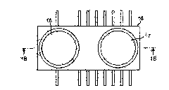
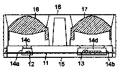
[0097] Hereinafter, this invention will be described in detail with reference to illustrated embodiments. Figure 1A And 1B is a figure which shows the schematic structure of the optical distance measuring sensor of this embodiment. in addition, Figure 1A is the floor plan, Figure 1B yes Figure 1A The arrows 1B-1B point to the sectional view.

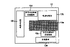
[0098] Such as Figure 1B As shown, in this optical distance measuring sensor, a light emitting element 12 and a light receiving element 13 composed of infrared LED (light emitting diode) or infrared surface emitting laser etc. are arranged on a lead frame (lead frame) 11 . here, as figure 2As shown, the light-receiving element 13 includes: a position detection light-receiving part 13a composed of m rows×n columns (m≥2, n≥2) of CMOS area sensors, CCD (charge-coupled device) area sensors or photodiode columns; The processing circuit part 13b that processes the signal output from the position detection light receiving part 13a; ...


PUM


Abstract

An optical ranging sensor includes a light emitting unit for projecting a light beam on an object to be measured, a light receiving unit on which a light spot of reflected light of the light beam from the object is formed, and a processing circuit unit for processing output signals from the light receiving unit and detecting a distance to the object. The light receiving unit includes an effective light receiving part having light receiving cells arranged in matrix form in a first direction in which a position of the light spot moves as the object moves along a direction of an optical axis of the light emitting unit, and in a second direction orthogonal to the first direction. A size of the effective light receiving part in the second direction is not smaller than a radius of the light spot but not larger than a diameter thereof.

Description

technical field [0001] The present invention relates to an optical distance measuring sensor for detecting a distance to an object, and an electronic device equipped with the optical distance measuring sensor. Background technique [0002] Conventionally, as an optical distance measuring sensor for detecting the distance to an object, there are the following optical displacement measuring devices (JP-A-2002-195807: Patent Document 1) and optical displacement meters (JP-A-2006-38571 Publication: Patent Document 2): The light emitted from light-emitting elements such as laser diodes is collected by a light projecting lens, and the obtained light beam is irradiated to the object to be measured, and the light emitted by the object to be measured is collected by the light receiving lens. Part of the diffusely reflected light reflected from the surface forms light-receiving spots on the light-receiving surface of the MOS (metal oxide semiconductor) image sensor, and detects the di...

Claims


Application Information

Patent Timeline
Patent Type & Authority Applications(China)
IPC IPC(8): G01C3/00
CPCG01C3/085
Inventor 山口阳史和田秀夫久保胜吕志宏
Owner SHARP KK
Learn More