
Sputtering target and preparation method thereof

A sputtering target and oxide technology, applied in the field of sputtering targets, can solve the problems of flat target cracks, backplane warpage, and high coating stress

Inactive Publication Date: 2011-10-05
HERAEUS MATERIALS TECHNOLOGY GMBH & CO KG
View PDF11 Cites 9 Cited by
  • Summary
  • Abstract
  • Description
  • Claims
  • Application Information

AI Technical Summary

Problems solved by technology

[0010] Spraying onto a flat target does not give the desired thickness of 6mm to 10mm due to high stresses within the coating causing the backing to warp
This will cause severe cracks in the planar target

Method used


Image

  • Sputtering target and preparation method thereof
  • Sputtering target and preparation method thereof
  • Sputtering target and preparation method thereof

Examples


Embodiment 1

[0059] A sputtering target preparation method according to an exemplary embodiment of the present invention may include the following steps:

[0060] Dry mixing of metal oxide powders with metal powders, and

[0061] • Shaping the mixture by hot pressing or hot isostatic pressing.

[0062] In these exemplary embodiments, the metal powder may preferably be 10% by mass to 20% by mass. This is for pervasive distribution. The particle size of the metal oxide powder and the metal powder is preferably 1 μm to 150 μm. Segregation after mixing must be avoided by careful optimization between metal and oxide particle size, shape and density. Depending on the oxide used, it may be preferable to shape the mixture at temperatures between 600°C and 1400°C.

Embodiment 2

[0064] A sputtering target preparation method according to yet another exemplary embodiment of the present invention may include the following steps:

[0065] mixing metal oxide powders with metal powders into a slurry, and

[0066] Carry out spray drying;

[0067] shaping the mixture by pressing; and

[0068] • Carry out sintering in an inert atmosphere or in vacuum.

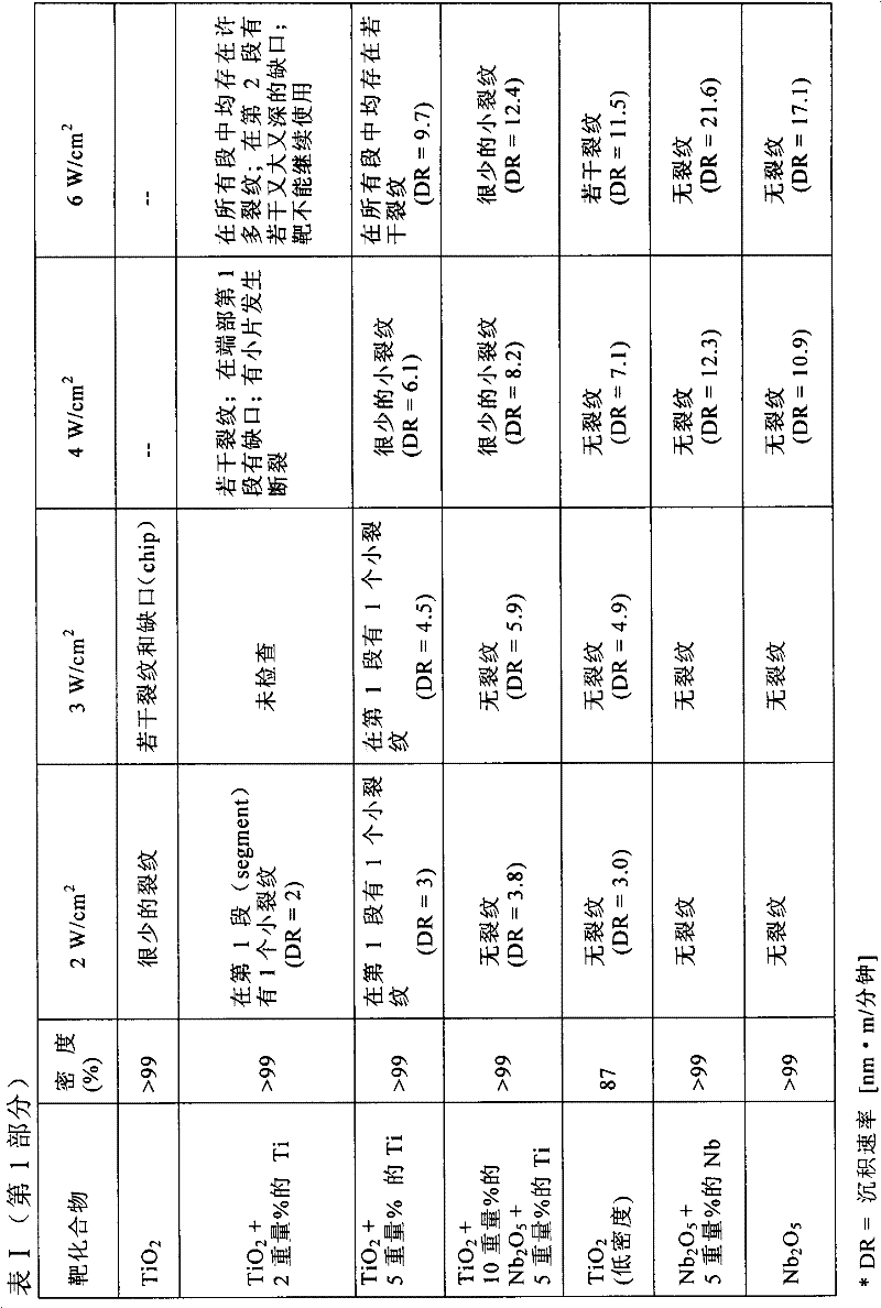
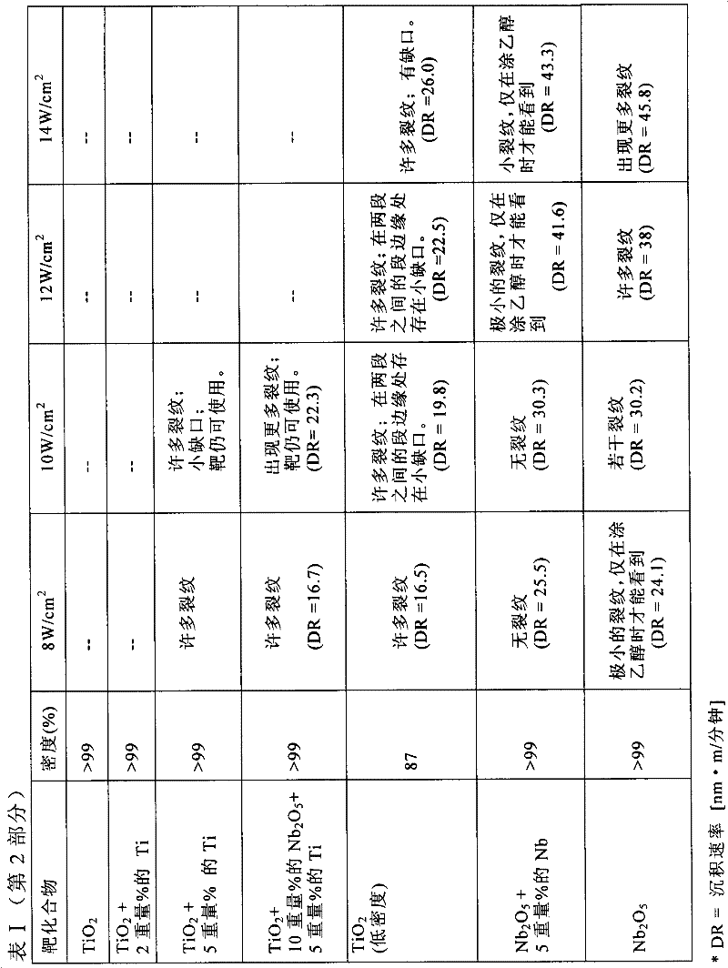
[0069] In these exemplary embodiments, the slurry may include a solvent, where the solvent may be water or any alcohol. During the implementation of the sputtering target preparation method, sputtering targets with different densities can be obtained by changing sintering parameters (eg, temperature and time). In this way, low-density sputtering targets with a density of 70% to 95%, preferably 80% to 95%, can be produced.

Embodiment 3

[0071] A sputtering target preparation method according to yet another exemplary embodiment of the present invention may include the following steps:

[0072] Mix metal oxide powder or a mixture of several metal oxide powders into a slurry,

[0073] Carry out spray drying;

[0074] shaping the mixture by pressing; and

[0075] • Carry out sintering in an inert atmosphere or in vacuum.

[0076] In these exemplary embodiments, the slurry may include a solvent, where the solvent may be water or any alcohol. During the implementation of the sputtering target preparation method, sputtering targets with different densities can be obtained by changing sintering parameters (eg, temperature and time). In this way, low-density sputtering targets with a density of 70% to 95%, preferably 80% to 95%, can be produced.


PUM

PropertyMeasurementUnit
Particle sizeaaaaaaaaaa

Abstract

The invention relates to a sputtering target and the preparation method thereof, wherein the sputtering target comprises a matrix material containing a first oxide of high refractive index and metallic components. The first oxide is selected from the group composed of titanium oxides of any variant forms, niobium oxides of any variant forms, vanadium oxides of any variant forms, yttrium oxides of any variant forms, molybdenum oxides of any variant forms, zirconium oxides of any variant forms, tantalum oxides of any variant forms, tungsten oxides of any variant forms, hafnium oxides of any variant forms, and the mixture thereof. The composition also contains a second oxide is selected from the group composed of lanthanides oxides of any variant forms, scandium oxides of any variant forms, and lanthanum oxides of any variant forms. The matrix material has apertures, and the sputtering target is applied for sputtering under high power density.

Description

technical field [0001] Broadly, the present invention relates to sputtering targets, and more particularly to sputtering targets comprising oxides having a high refractive index, which can be used for sputtering at high power densities. The invention also relates to the composition of the sputtering target and the preparation method of the sputtering target. Background technique [0002] The sputtering process involves ions being accelerated towards a target (called the sputter target); when the ions strike the target, the momentum of the ions is transferred to the target, causing atoms or molecules to escape from the surface of the target . These escaped atoms or molecules themselves are then deposited on the desired surface or substrate. Sputtering technology is often used to coat surfaces, especially for thin-film coatings. [0003] Sputtering targets made of different materials often determine the properties of the coating. For example, in order to obtain anti-reflec...

Claims


Application Information

Patent Timeline
IPC IPC(8): C23C14/34C23C14/06B22F3/16B22F3/02
CPCB22F2998/10B22F2303/01C22C1/053B22F2999/00B22F2998/00C22C29/12C23C14/3414B22F2302/25B22F2301/20C22C1/08C22C1/05B22F3/15B22F3/10B22F2201/02B22F2201/10B22F2201/20B22F1/145B22F3/02B22F2201/04B22F2201/013C23C14/34C23C14/08B22F3/12
Inventor M·施洛特A·赫尔佐克S·施奈德-贝茨白向钰O·罗伊朵
Owner HERAEUS MATERIALS TECHNOLOGY GMBH & CO KG
Learn More