Method for manufacturing phase zone plate

A zone plate and phase-type technology, which is applied in the field of plasma vapor deposition technology to produce phase-type zone plates, can solve the problems of low diffraction efficiency and achieve the effects of improving diffraction efficiency, simple manufacturing process, and low manufacturing cost

Inactive Publication Date: 2011-10-05
INST OF MICROELECTRONICS CHINESE ACAD OF SCI
View PDF3 Cites 5 Cited by
  • Summary
  • Abstract
  • Description
  • Claims
  • Application Information

AI Technical Summary

Problems solved by technology

[0005] The traditional zone plate manufacturing process often produces alternating transparent and opaque rings with the same area. The opaque ones are originally used to block light that is odd or even multiples of half-wavelength, while the transparent part is used to transmit even-numbered multiples of half-wavelength. Or odd multiples of light, and they block the general area, so the diffraction efficiency is lower than 50%

Method used


Image

  • Method for manufacturing phase zone plate
  • Method for manufacturing phase zone plate
  • Method for manufacturing phase zone plate

Examples


Embodiment Construction

[0031] In order to make the object, technical solution and advantages of the present invention clearer, the present invention will be described in further detail below in conjunction with specific embodiments and with reference to the accompanying drawings.

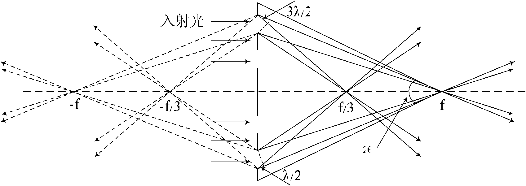
[0032] The invention uses the difference between the refractive index of light in silicon nitride and the refractive index in air to transform the phase of light, thereby making a zone plate with high diffraction efficiency.

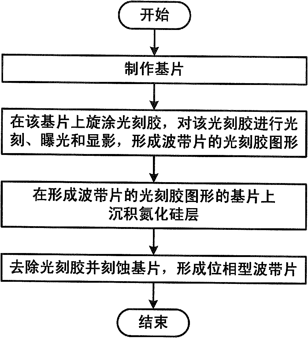
[0033] Such as figure 2 as shown, figure 2 It is a flow chart of a method for producing a phase zone plate provided by the present invention, the method comprising:

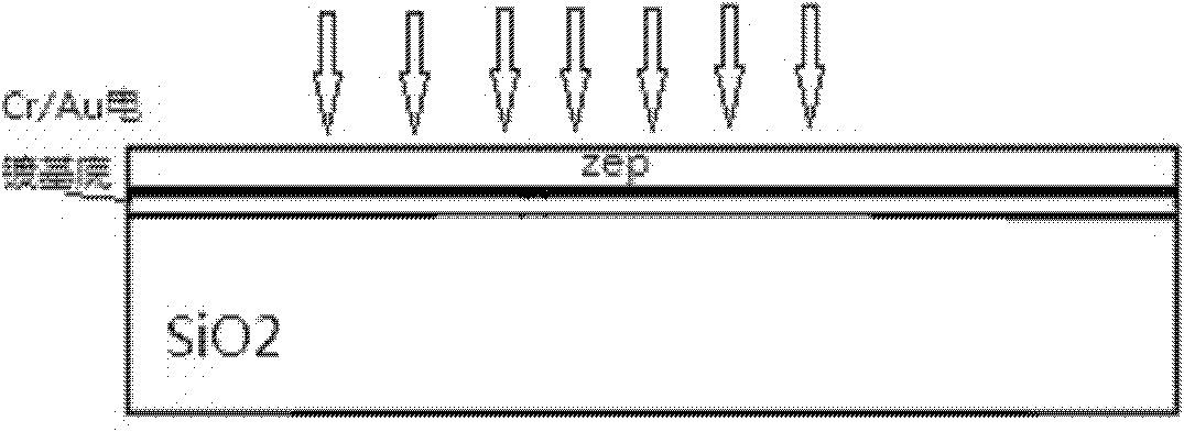
[0034] Step 1: making the substrate;

[0035] Step 2: Spin-coat photoresist on the substrate, perform photolithography, exposure and development on the photoresist, and form a photoresist pattern of the zone plate;

[0036] Step 3: depositing a silicon nitride layer on the substrate forming the photoresist pattern of the zone plat...


PUM


Abstract

The invention discloses a method for manufacturing a phase zone plate, which comprises the following steps of: manufacturing a substrate; performing spin coating of a photoresist on the substrate, and photo-etching, exposing and developing the photoresist to form a photoresist pattern of a zone plate; depositing a silicon nitride layer on the substrate on which the photoresist pattern of the zone plate is formed; and removing the photoresist and etching the substrate to form the phase zone plate. Compared with the conventional zone plate manufacturing technology, the method for manufacturing the phase zone plate is simple in manufacturing technology, low in cost and can improve the diffraction efficiency of the zone plate.

Description

technical field [0001] The invention relates to the technical field of manufacturing diffractive optical elements, in particular to a method for manufacturing a phase-type zone plate by using plasma vapor deposition (PECVD) technology. Background technique [0002] A zone plate is essentially a diffraction grating that can generate many diffraction orders. Whenever the light passes through the circular boundary of the connecting line, the optical path difference is mλ / 2 (m is an integer). figure 1 Give the light paths of the first and third focal points when a monochromatic plane wave illuminates a zone plate. Negative diffraction orders also exist, corresponding to rays emerging from a virtual focal point. Theoretically, a zone plate can have an infinite number of focal points: [0003] f m = f m - - - ( 1 ) [0004] In formu...

Claims


Application Information

Patent Timeline
Patent Type & Authority Applications(China)
IPC IPC(8): G02B5/18G02B7/00
Inventor 谢常青方磊朱效立李冬梅刘明
Owner INST OF MICROELECTRONICS CHINESE ACAD OF SCI
Why Eureka
Try Eureka