Sludge treatment and disposal system and method

A sludge treatment and disposal system technology, which is applied in dehydration/drying/thickened sludge treatment, combustion methods, lighting and heating equipment, etc., can solve the problem of low utilization rate of heat value of direct incineration dewatered sludge and unusable sludge Problems such as low calorific value and low heat contribution rate of organic matter can achieve the effects of saving infrastructure costs and high-quality energy, solving difficult disposal, and reducing drying costs

Active Publication Date: 2011-10-12
国能朗新明环保科技有限公司
View PDF2 Cites 22 Cited by
  • Summary
  • Abstract
  • Description
  • Claims
  • Application Information

AI Technical Summary

Problems solved by technology

[0005] The main issue of the debate is that the water content and addition rate of sludge have a great influence on the thermal efficiency of the incineration boiler. The higher the water content of the sludge, the lower the calorific value and the smaller the thermal contribution rate. The sludge with a water content of 80% The heat contribution rate to power generation is very low, and the heat value utilization rate of direct incineration of dewatered sludge is extremely low. Not only can the heat value of organic matter in sludge not be utilized, but a large amount of high-quality fuel needs to be supplemented as a combustion aid

Method used


Image

  • Sludge treatment and disposal system and method
  • Sludge treatment and disposal system and method
  • Sludge treatment and disposal system and method

Examples


Embodiment Construction

[0032] Embodiments of the present invention are described in detail below, examples of which are shown in the drawings, wherein the same or similar reference numerals designate the same or similar elements or elements having the same or similar functions throughout. The embodiments described below by referring to the figures are exemplary only for explaining the present invention and should not be construed as limiting the present invention.

[0033] In the description of the present invention, the orientations or positional relationships indicated by the terms "upper", "lower" and the like are based on the orientations or positional relationships shown in the accompanying drawings, which are only for the convenience of describing the present invention and do not require that the present invention must be based on a specific Azimuth configuration and operation, therefore, should not be construed as limiting the invention.

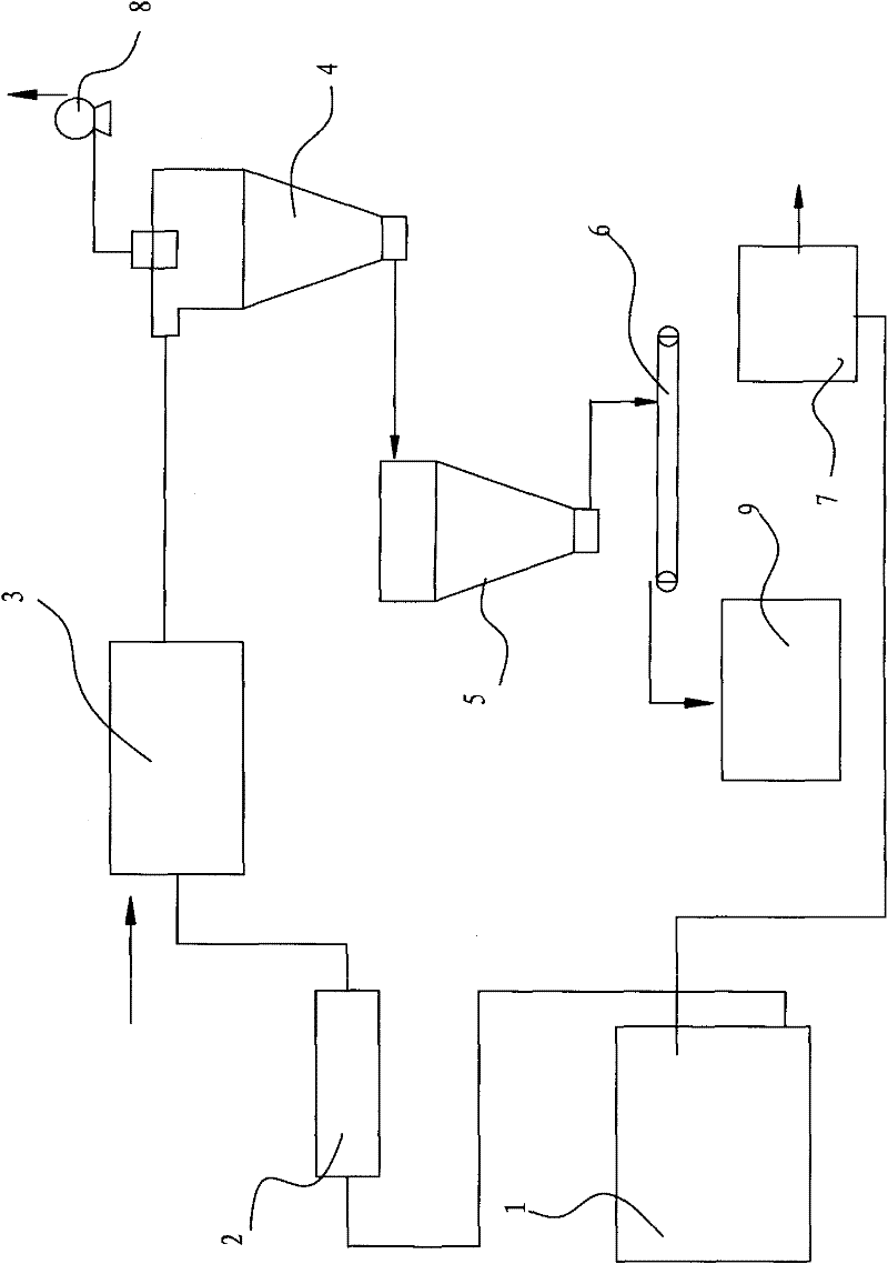
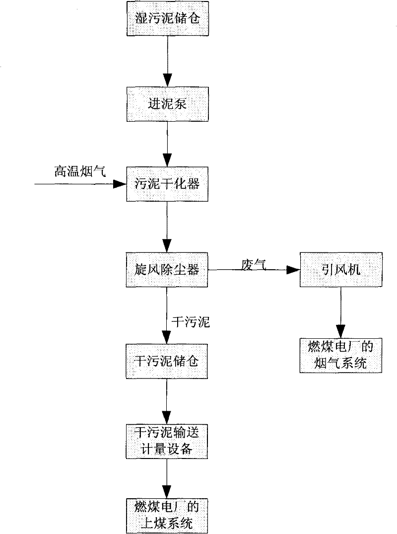
[0034] Refer below figure 1 The sludge treatment and...


PUM


Abstract

The invention discloses a sludge treatment and disposal system, which is used for conveying dewatered sludge discharged by a sludge plant to a coal fired power plant to be combusted in a blended way after the dewatered sludge is dried. The sludge treatment and disposal system comprises a wet sludge storage bin, a sludge dryer, a sludge feeding pump, a cyclone dust collector, a dried sludge storage bin, dried sludge conveying equipment and a draught fan. The sludge feeding pump is respectively connected with the wet sludge storage bin and the sludge dryer. The cyclone dust collector is communicated with the sludge dryer so as to perform gas-solid separation on dried sludge and waste gas of the dryer. The dried sludge storage bin is connected with the cyclone dust collector so as to receivethe separated dried sludge. The dried sludge conveying equipment is connected with the dried sludge storage bin and used for conveying the dried sludge to a coaling system of the coal fired power plant. The draught fan is connected with a waste gas hole of the cyclone dust collector. According to the sludge treatment and disposal system disclosed by the invention, the sludge treatment and disposal cost can be effectively reduced; vast high-quality resources can be saved; and a way of using waste to treat waste is realized. The invention further discloses a sludge treatment and disposal method.

Description

technical field [0001] The invention relates to the field of solid waste treatment in the field of environmental protection, in particular to a sludge treatment and disposal system and a sludge treatment and disposal method using the system. Background technique [0002] Sludge is an inevitable product of sewage treatment in urban sewage treatment plants. It is huge in quantity, complex in composition, difficult to treat, and the cost of sludge disposal is also relatively high. The purpose of sludge treatment is to achieve reduction, stabilization, harmlessness and recycling. More mature sludge treatment methods include landfill, composting and incineration. [0003] Incineration is to fully burn the combustible components in the sludge at high temperature, and finally become stable ash. The incineration method has the advantages of high volume reduction, high weight reduction rate, fast processing speed, complete harmlessness, and waste heat can be used for power generatio...

Claims


Application Information

Patent Timeline
Patent Type & Authority Applications(China)
IPC IPC(8): C02F11/12F23G7/00
Inventor 徐奎江程日旺申欢张立张世乾梁梦晓
Owner 国能朗新明环保科技有限公司
Why Eureka
Try Eureka