Filter

A filter and dielectric resonator technology, applied in waveguide devices, electrical components, circuits, etc., can solve the problems of high filter failure risk, high long-term reliability risk, small thermal expansion coefficient, etc., and achieve the goal of reducing cracking phenomenon Probability, guaranteed reliability, and the effect of improving the life of solder joints

Inactive Publication Date: 2011-10-19
HUAWEI MACHINERY
View PDF4 Cites 17 Cited by
  • Summary
  • Abstract
  • Description
  • Claims
  • Application Information

AI Technical Summary

Problems solved by technology

[0002] Filter is an important component commonly used in communication engineering. It has frequency selectivity to signals, and passes or blocks, separates or synthesizes signals of certain frequencies in the system. The resonant cavity of a dielectric filter is mainly composed of a dielectric resonator and a cavity The dielectric resonator refers to an electronic component that generates a resonant frequency. It has many resonant modes, and the electromagnetic field of the dielectric comb line resonant mode is similar to the electromagnetic field of the metal comb line resonant mode. Compared with other modes, Q( The parameters of the inductance device) are high, and it is easy to make a high-performance filter; while in the resonant cavity of the dielectric comb line filter, one end of the dielectric resonator is welded to the bottom wall of the cavity, the other end of the dielectric resonator is suspended, and the dielectric resonator and The connection quality of the cavity is directly related to the performance (frequency, insertion loss, intermodulation) and reliability of the filter, especially the change of the contact area between the end face of the dielectric resonator and the surface of the cavity will lead to the deterioration of the electrical performance
[0003] In the existing technology, the mainstream cavity materials are low-cost, easy-to-form aluminum alloys and magnesium alloys with relatively low density. Recently, engineering plastics are also used as cavity materials. The commonality of these materials lies in their The thermal expansion coefficient (CTE) is generally large, and the dielectric resonator is made of ceramic material, and its thermal expansion coefficient is small. Because the operating temperature of the front-end of the communication equipment transceiver changes greatly, as the power capacity of the filter increases, the dielectric The solder joints welded between the resonator and the cavity are cracked and loose due to the large difference in thermal expansion coefficient, which brings about increasing long-term reliability risks and ultimately brings a higher risk of filter failure

Method used


Image

  • Filter
  • Filter
  • Filter

Examples


Embodiment 1

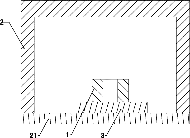
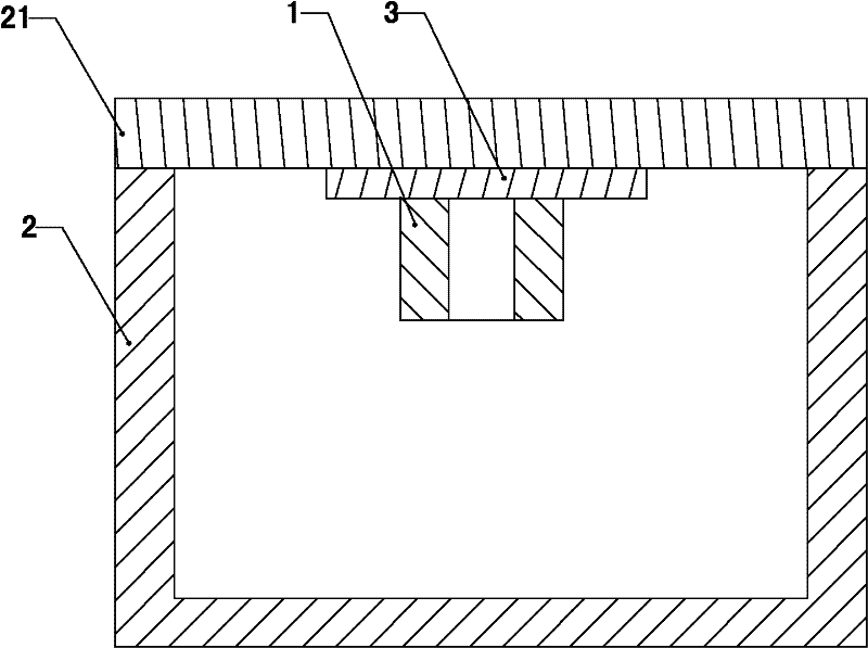
[0027] See figure 1 , The filter of the embodiment of the present invention includes a dielectric resonator 1, a cavity 2 and a connector 3. The dielectric resonator 1 is installed in the cavity 2, and the dielectric resonator 1 is welded to the connector 3 and connected The part 3 is connected to the cavity 2 and the dielectric resonator 1 is not in direct contact with the cavity 2; in this way, the connection between the dielectric resonator 1 and the cavity 2 through the connector 3 is formed. The design of the connector 3 can be as follows One or two of the solutions:

[0028] First, the difference between the thermal expansion coefficient of the connecting piece 3 and the thermal expansion coefficient of the dielectric resonator is smaller than the difference between the thermal expansion coefficient of the cavity 2 and the thermal expansion coefficient of the dielectric resonator.

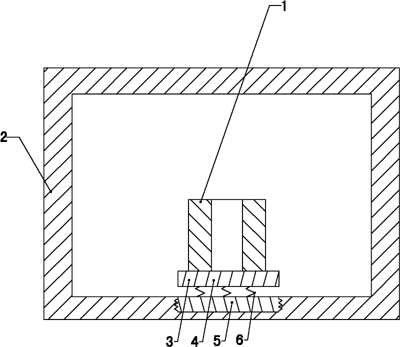
[0029] Second, the connecting member 3 is a deformation buffer structure with an elastic defor...

Embodiment 2

[0042] The filter of the embodiment of the present invention may also adopt another design, as follows:

[0043] See Figure 5 , The filter of the embodiment of the present invention includes a dielectric resonator 1 and a cavity 2. The dielectric resonator 1 and the cavity 2 are welded together. The cavity 2 is a sheet metal part. The material of the cavity 2 is directly replaced. For sheet metal parts with a smaller thermal expansion coefficient, the CTE of the sheet metal parts is generally small, which is close to the ceramic material of the dielectric resonator 1. In this way, the reliability of the solder joints of the dielectric resonator can be guaranteed and the dielectric resonator 1 and the cavity can be reduced. The probability of body 2 cracking due to the difference in thermal expansion coefficient.

[0044] In the above design, in order to provide a specific design of sheet metal parts that can be implemented, the sheet metal parts in the filter of the present invent...

Embodiment 3

[0046] See Picture 10 , The filter of the embodiment of the present invention includes a dielectric resonator 1 and a cavity 2. The dielectric resonator 1 and the cavity 2 are welded together, and the weld 10 between the dielectric resonator 1 and the cavity 2 is provided with columnar reinforcement The two ends of the reinforcing member 11 are welded to the dielectric resonator 1 and the cavity 2 respectively, and the area where the reinforcing member 11 is not provided at the welding seam 10 is filled with the above-mentioned solder 12, so that the reinforcing member 11 can be installed Increasing the thickness of the welding seam 10 can increase the life of the welding joint to a certain extent, and ultimately reduce the probability that the dielectric resonator 1 and the cavity 2 will crack due to the difference in thermal expansion coefficient.

[0047] In the filter of the embodiment of the present invention, the columnar reinforcement 11 is provided with a plurality of hol...


PUM


Abstract

The invention discloses a filter relating to the field of communication equipment. The filter can reduce the possibility that a welding spot of a medium resonator is cracked owning to the difference of thermal expansion coefficient. The filter provided by the embodiment of the invention comprises a medium resonator, a chamber body and a connecting piece, wherein the medium resonator is arranged in the chamber body; the medium resonator is welded on the connecting piece that is connected with the chamber body together; the medium resonator is not directly contacted with the chamber body; the difference of the thermal expansion coefficient of the connecting piece and the thermal expansion coefficient of the medium resonator is less than that of the thermal expansion coefficient of the chamber body and the thermal expansion coefficient of the medium resonator, and / or the connecting piece is a deformation damping structural part with the elastic deformation capability higher than that of the chamber body. The filter is applied to the design concept on a novel filter and is mainly applied to a novel comb-shaped linear medium resonation mode.

Description

Technical field [0001] The invention relates to the field of communication equipment, in particular to a dielectric filter. Background technique [0002] The filter is an important component commonly used in communication engineering. It has frequency selectivity for signals. It passes or blocks, separates or synthesizes signals of certain frequencies in the system. The resonant cavity of a dielectric filter is mainly composed of a dielectric resonator and a cavity. Dielectric resonator refers to the electronic component that produces the resonant frequency. It has many resonant modes. The electromagnetic field of the dielectric comb-line resonance mode is similar to the electromagnetic field of the metal comb-line resonance mode. Compared with other modes, Q( The parameter of the inductance device is high, and it is easy to make a high-performance filter; while in the dielectric comb-line filter cavity, one end of the dielectric resonator is welded to the bottom wall of the cavi...

Claims


Application Information

Patent Timeline
Patent Type & Authority Applications(China)
IPC IPC(8): H01P1/207H01P1/30
Inventor 梁英
Owner HUAWEI MACHINERY
Why Eureka
Try Eureka