Process for producing sintered ore and sintering apparatus

A manufacturing method and technology of sintering, applied in the direction of furnace, furnace type, lighting and heating equipment, etc., can solve the problems of high risk, poor ventilation, and inability to fully reflect the blowing of flammable gas

Active Publication Date: 2011-11-09
JFE STEEL CORP
View PDF12 Cites 11 Cited by
  • Summary
  • Abstract
  • Description
  • Claims
  • Application Information

AI Technical Summary

Problems solved by technology

However, this method also has a high risk of fire in the upper space of the sintering bed because the flammable gas is blown in the state where the flame remains on the surface. In addition, the width of the sintering zone cannot be made sufficiently thick (less than about 15 mm). , so it cannot fully reflect the effect of blowing inflammable gas
Moreover, since a large amount of low-melting-point solvents exists, excessive melting occurs in the upper layer, clogging the pores as air flow paths, deteriorating air permeability, and lowering productivity. Therefore, this technology has not been put into practical use yet.
[0013] As mentioned above, all the conventional technologies proposed so far have serious problems in terms of practical use, so the development of a practicable flammable gas injection technology is eagerly awaited

Method used


Image

  • Process for producing sintered ore and sintering apparatus
  • Process for producing sintered ore and sintering apparatus
  • Process for producing sintered ore and sintering apparatus

Examples


Embodiment Construction

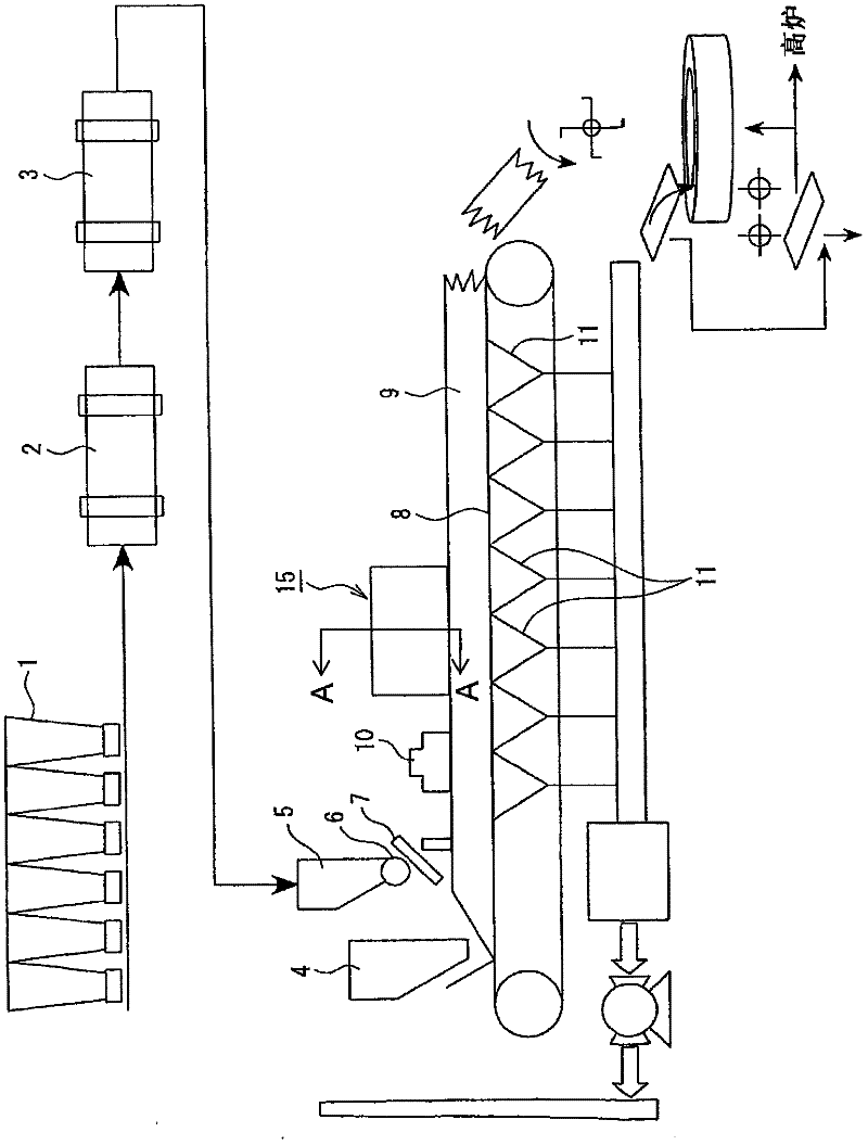
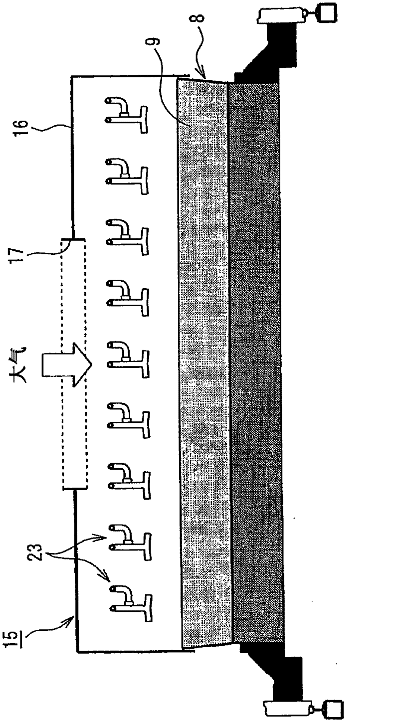
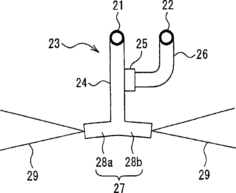
[0073]The method for producing sintered ore using the sintering machine of the present invention includes a charging step, an ignition step, a liquid fuel supplying step, and a sintering step. In this manufacturing method, the above-mentioned loading process is a process of loading the sintered raw material containing powdered ore and carbon materials on a trolley that moves in circulation to form a filling layer of the sintered raw material on the trolley; the above-mentioned ignition process is to use an ignition furnace to The process of igniting the carbon material on the upper surface of the packing layer. In addition, the above-mentioned liquid fuel supply process is a process of injecting liquid fuel atomized to 100 μm or less from a liquid fuel injection device to the upper side of the packed bed; The atomized liquid fuel and air are sucked into the packed layer, and the atomized liquid gaseous fuel is burned in the packed layer, and at the same time, the carbon materi...


PUM

PropertyMeasurementUnit
particle diameteraaaaaaaaaa
particle sizeaaaaaaaaaa

Abstract

A process for sintered-ore production in which high-quality sintered ore having high strength can be safely produced in a high yield with a sintering apparatus of a downward suction type; and the sintering apparatus. The process for sintered-ore production comprises: placing a raw material to be sintered comprising fine ore and a carbon material, on a circulating pallet (8) to form a raw-material layer (9); igniting the carbon material of the raw-material layer in an ignition furnace; and sucking air with a wind box disposed under the pallet to thereby produce sintered ore. After the raw-material layer (9) has been ignited in the ignition furnace, a liquid fuel is atomized to a particle size of 100 [mu]m or smaller and supplied to over the raw-material layer (9), and the atomized liquid fuel is supplied from over the raw-material layer (9) into the raw-material layer (9) after having been diluted at least to the lower limit of ordinary-temperature combustion concentrations. The sintering apparatus has, disposed downstream from the ignition furnace, a liquid-fuel injector which injects the liquid fuel over the raw-material layer.

Description

technical field [0001] The present invention relates to a method for producing sintered ore and a sintering machine for producing sintered ore. Background technique [0002] As the main raw material for blast furnace ironmaking, sintered ore is usually Figure 15 Manufactured by the process shown. The raw materials for sintering are iron ore powder, recycled powder in ironworks, sinter under-sieve powder (returned ore), limestone and dolomite and other CaO-containing auxiliary materials, quicklime and other granulation aids, coke powder, anthracite, etc. These raw materials are respectively cut out by a plurality of hoppers 1 onto the conveyor belt at predetermined ratios. The cut raw materials are mixed and granulated by adding an appropriate amount of water through the drum mixer 2, rotary kiln 3, etc., to produce quasi-particle sintered raw materials with an average particle diameter of 3.0 to 6.0 mm. On the other hand, the lump ore after sizing is cut out from the furn...

Claims


Application Information

Patent Timeline
Patent Type & Authority Applications(China)
IPC IPC(8): C22B1/20F27B21/08
CPCF27B21/02C22B1/205F27B21/06C22B1/20F27B19/00
Inventor 大山伸幸岩崎克博
Owner JFE STEEL CORP
Why Eureka
Try Eureka